Single transformer.
still at first morning coffee ( it doesn't matter that noon is already ) , but it looks pretty good
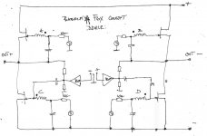
something like that I had in mind , asking you to toss redundant xformer ; now just few possible iterations , focusing on feedback , to make it SUSY
like this, it isn't
disclaimer - first morning coffee ....... I'm sure later I'll see Triffids on schematic