you should try that with two already made pcbs
matter of one wire
or not even that ; careful measurement will only tell is it any gain in common feedback arrangement ( for two halves of balanced ) vs. regular fdbck against real gnd scheme
think of function of McMilan resistors ; in some balanced configurations/parts values combos they're more effective , in some are almost zilch effective
Have them sitting right here waiting on parts. Doesnt value play into this dance.
Last edited:
So I have a question before bed. If error current is introduced into source of complimentary source followers, is it doing any good, as the signal is not taken from the drain? It would seem that any correction that might be gained will run smack into the "corrected signal"
Mcmillan resistor is not well explained in my findings. It seems to be a point of control over the reaction of the two halves, increasing or diminishing the effectiveness of the error current.
Mcmillan resistor is not well explained in my findings. It seems to be a point of control over the reaction of the two halves, increasing or diminishing the effectiveness of the error current.
So I have a question before bed. If error current is introduced into source of complimentary source followers, is it doing any good, as the signal is not taken from the drain? It would seem that any correction that might be gained will run smack into the "corrected signal"
Mcmillan resistor is not well explained in my findings. It seems to be a point of control over the reaction of the two halves, increasing or diminishing the effectiveness of the error current.
as I already wrote to you - some of these things are hard for me to shape in writing ; however - signal taken from the drain isn't conditio sine qua non for feedback function , as you know .
observe one half - you can make it in myriad of ways , especially considering FB route ; if you're able to connect two identical halves in way that returning feedback is going to each input(better put - influencing each input ) from other halve's output , that's SUSY ; so - just think polarity and FB injecting point and condition of crossfeedback
any further explanation will lead me to public yukyuk about Ultrasymmetry ( thing still not existing in any amp in our Universe and neighboring ones ) and I don't wanna do that
thought ...... to complicate things further - conceptually - you can imagine these two complementary buffers as sort of twisted (gainless ) nasty UGSess
gollumgollum
Last edited:
I was even thinking about ZV6 and how Nelson talked about the fact that SUSY was more effective in two stage topologies, meaning gain stages, I assume. THis is just single stage as it sits. But moi haev an idea. Look at it this way. I am only a decade behind current developement

..... THis is just single stage as it sits......
yes and no
it's having phase splitter and gain stage ; so sort of two
however - I'm not digging that condition of two stages
maybe he said that you need to have one left and one right stage , for SUSY

one LTP is enough for Full Monty
what is hard , is - to make it simpler that that
edit - just came to my mind - I remember seeing looong time ago schematics in yore periodics - it seems that xformer stereo matrix gadgets had some sort of X feedback , in starting era of Stereo ; so - there was no even LTP in them , at least not "active" ones
Last edited:
Transformers make my brain hurt. I can see how they would be perfect in the sense that they are, in themselves a sort of balancing act, as you say. But what to do with the dman things in this situ.
buzzforb. Your PCB is a piece of art too. I hope that you'll have a future kit with it.My little freak.
nice
now - do the same , but with just one xformer

Zen Mod. I wrote a schematic for a bridge diyF6 using one transformer [post #3619]. It had limitations:
- one end of the brige is a voltage source amp while the other end is current source amp.
- A coupling cap to the gate of the bottom JFET of the current source amp.
I have a general comment on bridge amps. Bridge F6 with F5 or bridge F5 with L'Amp a simple SIT ala Rothacher, or bridge an SE triode amp with a SIT. One has a fertile ground to treat its hearing to the best amps of highest state of the art and science. Does anybody see anything irregular with this approach?
Your designs are meticulous. To me, the proper phase of the signals in the guts of the circuit is the most important criterion for it to work or not. Synchronicity!Might not be worth circuit board it is printed on. Easy enough to try once parts come in.
Here is my approach to FW amps.
I believe ZM taught me this.
Take all ground wires from Speakers , line signal and and solder all to PS ground at back end, In the middle of the V+ and V- outputs. In that same area, take CL60 and tie that to chassis ground with bolt, and from there, bolt wire to IEC power cord ground.
So a CL60 seperates everything from direct chassis or IEC ground.
From here, shorting the inputs should lead to a quite amp. If not. Twist toriod, or cover toriod and or the Jensen's with MU-Metal (careful not to short).
Is your setup different?
So are you saying not to use any of the in/out ground points on the amp PCB?
I also assume then to only run one gnd wire from amp board to PSU ground and run input /output ground wires only directly to PSU board gnd? Then PSU board gnd to cl60 to star gnd?
Hi cjkpkg,
Still the hum it seems....one idea got in my mind some days ago....
The current through the F6 circuit goes up very quick turning the pot....
Is it possible that you have more than 1.5A let's say 2A ore even more...😱
Happened sometimes to me......🙂
Still the hum it seems....one idea got in my mind some days ago....
The current through the F6 circuit goes up very quick turning the pot....
Is it possible that you have more than 1.5A let's say 2A ore even more...😱
Happened sometimes to me......🙂
So are you saying not to use any of the in/out ground points on the amp PCB?
I also assume then to only run one gnd wire from amp board to PSU ground and run input /output ground wires only directly to PSU board gnd? Then PSU board gnd to cl60 to star gnd?
Yes, although I realize the board is designed to handle a direct ground, and then one wire ground to PS ground. Usually there is no problem either way, and I tested both. I wonder if you can uncouple a channels heatsink and stretch the wires out if you will, if the hum is redunced. This may tell us if it is coming from another components, or is just a ground loop.
My amp builds are generally dual mono. Their central star grounding points where all ground connections meet, is always the ground rails of the capacitors banks, irrespective of passive or regulated power supplies. The chassis ground is connected via NTCs.
There is one exception yet. The signal grounds from the input terminals lead directly to the amp boards.
It is always dead silent and absolutely hum free.
There is one exception yet. The signal grounds from the input terminals lead directly to the amp boards.
It is always dead silent and absolutely hum free.
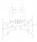
buzzforb. You show an interesting schematic.Single transformer.
The big question is the modulation of the second stage. I believe this or the first circuit could be operated with no local feedback and achieve very respectable numbers. In my very short stint in audio, there is something very alluring about minimalist circuts that perform well. There is simply more information and space conveyed in the playback. I was quite shocked when listening to the original F6 how much removing the source resistors seemed to open things up. Sure we have feedback, but it does not seem to be causing any nasties that come through. I am going to be trying both the firs circuit and this one, as I am unsure if either holds an advantage. FE on this one will be cascoded with LEd rferemce so I can run Jfets at miminal degeneration. All options and configurations will be included for playing. I am even trying prganic polymer as coupling cap in output as I am interested to see how these perform/sound vs standard electrolytics.
buzzforb. You show an interesting schematic.
Little spin on your suggestion.
- Home
- Amplifiers
- Pass Labs
- F6 Amplifier