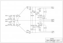
The shunt regulator was tested and adjusted to the +-32 V on both channels.Positive and negative output voltages are quite indentical and the adjustmen was done only with one trimmer pot per channel.
Here are the final circuit diagram and PCB layout. The circuit diagram shows one channel of the CCS - shunt part, and PCB was made with separate supplys for the stereo channels.
Damir
Here are the final circuit diagram and PCB layout. The circuit diagram shows one channel of the CCS - shunt part, and PCB was made with separate supplys for the stereo channels.
Damir
Attachments
![shuntreg.LAY].jpg](/community/data/attachments/312/312863-584cf2deddcf0c977f8c7c0152ee1af8.jpg?hash=WEzy3t3PDJ)
Couldnt one put a three terminal regulator IC for the shunt portion ... across the line. the topology is similar.
Thx-RNMarsh
Thx-RNMarsh
Couldnt one put a three terminal regulator IC for the shunt portion ... across the line. the topology is similar.
Thx-RNMarsh
Yes probably, but could you suggest one to be used for 32V as a shunt.
And I will lose the feature of a simple adjustment both polarities with just one trimpot.
BR Damir
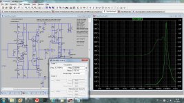
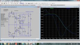
Great work! Could you post psrr and output impedance graph for the finall version?
Here are for the Gaiwire, but only simulated.
Attachments

Sorry, I meant for the sunt reg...
Look here http://www.diyaudio.com/forums/anal...onveyor-voltage-amplifier-20.html#post3373538
Yes probably, but could you suggest one to be used for 32V as a shunt.
And I will lose the feature of a simple adjustment both polarities with just one trimpot.
BR Damir
A series transistor with the 3-term shunt reg will keep the IC 3-term reg Ok to any voltage needed. Has anyone done this --- using two 3-term regs for a series/shunt reg circuit?
Thx-RNMarsh
I`ve seen that but thers no psrr graph?
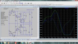
I asked yo becose I get different data in microcap. Do you measure it the same way with AC analysis?
db(v(OUT)/v(in)) where v(OUT) is the regulator output voltage and v(in) is ac voltage at the regulator input (before ccs).
db(v(OUT)/v(in)) where v(OUT) is the regulator output voltage and v(in) is ac voltage at the regulator input (before ccs).
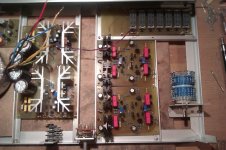

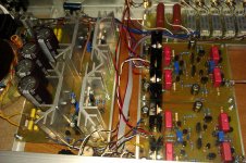
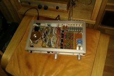
I am listening for a few days now this line/headphone amp and I am very, very satisfied with the music coming out of it.
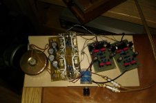
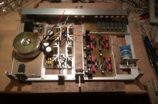
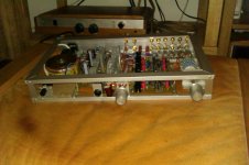
The skeleton and the muscle are finished and now I have to put some skin around it. Final schematic is here and some photographs too.
BR Damir
The skeleton and the muscle are finished and now I have to put some skin around it. Final schematic is here and some photographs too.
BR Damir
Attachments

I am listening for a few days now this line/headphone amp and I am very, very satisfied with the music coming out of it.
The skeleton and the muscle are finished and now I have to put some skin around it. Final schematic is here and some photographs too.
BR Damir
lucky you!😀
please send asc file for last version
thank you in advance
PS I am going to build it too as pre for power buffer, but when???🙄
lucky you!😀
please send asc file for last version
thank you in advance
PS I am going to build it too as pre for power buffer, but when???🙄
Thank you padamiecki,
Here is the last file.
BR Damir
Attachments
- Status
- Not open for further replies.
- Home
- Source & Line
- Analog Line Level
- Current conveyor as a voltage amplifier