So you are suggesting a series resistor prior to CCS made with BF245B; what would the typical value of the resistor be?
Why not use 2 transistor CCS or Transistor and LED, as an alternative?
Resistor would be Ur(V)/0,0024 A, where Ur is desired voltade drop on this serial resistor in this case 5-10 V. 😉
Because PSRR is way better in VSSA if j-fet CCS is used, since CCS Zout in this case is in a Gohm range.

2sk246/ 2sj103 BL grade ,
but why it has to be Idds 8mA ??
... 8 mA at Vgs=0 V, you have to have headroom for calibration with normal Rgs value, otherwise calibration is senseless. Also higher Id j-fet is much more stable in respect of Id current in this ratio of performance/stability target. 😎
Any type of N or P ch j-fet providing Id=8 mA at Vgs=0 V is OK, so when calibrated to cca. 2,4 mA as CCS in VSSA, Rgs at that point (two parallel fixed setting resistors) is in a range of 1 kohm.
The only limiting factor is Vds max, which at 2N5462 is 40 V. Solution is to put resistor in series with CCS to take few extra volts. I can consider this and implement BF245B plus serial resistor in a GB PCB since this one is easily obtainable.
BF245 is out of production
BF545 SMD 😀 is to be direct replacement
BF245 is out of production
BF545 SMD 😀 is to be direct replacement
I could replace TO-92 with SMD type since there's reasonably low 90 mW of power dissipation on each CCS j-fet. With serial resistor added we can programme it to 50 mW only.
Cat, how high a very good square this one can pass in SMD version?
Still didn't get there. Also this toroid now has secondary voltage of 2 x 24 Veff, enabling 2 x 33 V DC only. By the end of this week I'll get two 350 VA/2 x 29 Veff toroids and will perform squares measurements/plots, promise. 😉
2N5462 is available..
I think when when we have a GB it would be great to order all the semis from Digi-key or other distributor.
Probably we could get some price break if we order 100PC or so.
All do I will go with regular resisters, I do like the PRP resisters.
Price/sound one of the best choice to me.
Also I want to use silver solder which is not (higher temp melting) the best for SMD parts.
So I made my layout to use all regular part!
I want to compare these amp with my SSA amplifier..
It would only be fair to use same resisters, solder, wires etc to compare them.🙂
Greetings Gabor
Attachments
While SMD parts offer measurable advantages in speed and bandwitch due to less inductances (reduced path lengths) and less EMI/RFI sensibility(reduced surfaces), while the quality of the solder has no influence on sound, despite the audiophile legends, it seems you chose to compromise the overall quality for a bad reason.Also I want to use silver solder which is not (higher temp melting) the best for SMD parts.
Their is no sound of wires/metals, only lumped elements.
Now, everybody is free to fool himself, believing in magic.
While SMD parts offer measurable advantages in speed and bandwitch due to less inductances (reduced path lengths) and less EMI/RFI sensibility(reduced surfaces), while the quality of the solder has no influence on sound, despite the audiophile legends, it seems you chose to compromise the overall quality for a bad reason.
Their is no sound of wires/metals, only lumped elements.
Now, everybody is free to fool himself, believing in magic.
while the quality of the solder has no influence on sound,😛 despite the audiophile legends, it seems you chose to compromise the overall quality for a bad reason.
Their is no sound of wires/metals, only lumped elements.
Now, everybody is free to fool himself, believing in magic.
I do not believe in audio magic neither of snake oil but I do believe to my ears.
About the rest of your comment please tell someone who has no experience with components or DIY.
I build amps speakers etc over 25 years.😀
But I do not wish to argue over these nonsense.., not for a min. or a second!
Thank you for your cooperation!
Greetings Gabor
It would be a good idea, IMHO, to add on some versions of the VSSA's boards, places for a low RDSon MOSfets between rails and drains of the power fets, and place to fix an optical driver for them. Could be used for protection and silent start/stop, or by passed by straps.
See here: http://www.diyaudio.com/forums/solid-state/221737-ultimate-amp-protection-circuit-7.html
This proposal will make a protection perfect, as the non linearities (little) of the protection MOS will be canceled by the feedback.
See here: http://www.diyaudio.com/forums/solid-state/221737-ultimate-amp-protection-circuit-7.html
This proposal will make a protection perfect, as the non linearities (little) of the protection MOS will be canceled by the feedback.
Thanks!By default bias level 0,4 Wrms at 8 ohm, with good heatsink provided, bias can be trimmed to enable 1 Wrms/8 ohm class A without any problem.
Is it not possible to biasing more into Class A???
Greets:
Tyimo
Hi guys 
Esperado, It can be done of course but power-on start of VSSA is already absolutely silent. For protection purposes maybe in the next release. 🙄
Tyimo, I biased for the test and stability purpose to 1 A and it was OK. So if you like to have very HOT VSSA just go for it. 😀
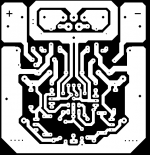
But first thing is to prepare 50 x 60 mm VSSA PCB to be perfectly DIY proof with parts available and to fit in without any nonsense.
As we all know TO-92 j-fets are commonly obsolete and unavailable so I'll put SOT-23 j-fets like BF545B to serve as CCSs from both sides of rails.
PCB is in preparation, also I check availability of ALF08NP16V5 as this is the most important part of VSSA and I think there will be no problem even if I have to order it at Semelab-TT directly.
This is current situation and progresses.
Regards, Andrej
Esperado, It can be done of course but power-on start of VSSA is already absolutely silent. For protection purposes maybe in the next release. 🙄
Tyimo, I biased for the test and stability purpose to 1 A and it was OK. So if you like to have very HOT VSSA just go for it. 😀
But first thing is to prepare 50 x 60 mm VSSA PCB to be perfectly DIY proof with parts available and to fit in without any nonsense.
As we all know TO-92 j-fets are commonly obsolete and unavailable so I'll put SOT-23 j-fets like BF545B to serve as CCSs from both sides of rails.
PCB is in preparation, also I check availability of ALF08NP16V5 as this is the most important part of VSSA and I think there will be no problem even if I have to order it at Semelab-TT directly.
This is current situation and progresses.
Regards, Andrej
Hi guys
Esperado, It can be done of course but start of VSSA is already absolutely silent. For protection purposes maybe in the next release. 🙄
Regards, Andrej
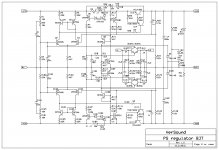
Maybe for the next release to use something as my PS Regulator. It incorporates all needed protection and acts as a capacitance multiplier.
dado
Attachments
Maybe for the next release to use something as my PS Regulator. It incorporates all needed protection and acts as a capacitance multiplier.
dado
Thank you dadod 😉
Looking to the complexity of the circuit it is quite clear it serves perfectly to job as it was intended. It is actually a slave amp supplying power to the master one. Maybe implemented in a High-End version of VSSA.
Thank you dadod 😉
Looking to the complexity of the circuit it is quite clear it serves perfectly to job as it was intended. It is actually a slave amp supplying power to the master one. Maybe implemented in a High-End version of VSSA.
Lazy Cat, I have two modified JLH MOSFET amps, and I was thinking to keep one and other one to convert to the VSSA or SSA as I don't have any CFB amp and never listened one.
By the way from JLH power supply for 80W MOSFET amp I 've get idea how to implement all needed protections. Different is that JLH use a voltage stabilizer and I use a regulator without fixed voltage reference. That JLH amp saved my speaker more than ones and like it a lot.
dado
... as I don't have any CFB amp and never listened one.dado
Dado
I thought JLH is CFB😕
Dado
I thought JLH is CFB😕
I was talking about JLH MOSFET 80W amp with classical LTP at the input.
My understanding is that Cat's design is - at the moment - complete and tested. It also appears to him to meet his requirement criteria. Admittedly I am a beginner with little knowledge but am old enough to stick to basics. Many of the proposed improvements from others - at the moment, - do not much more for the likes of me than muddy the water. I have on the other hand been party to testing of "off the wall designs", both DHT and solid state, by another revered designer. Some of these have been totally unacceptable to theorists, yet have been better - hands down - than anything which the technical guys have ever produced in terms of producing accurate sound. All of the protection circuits etc will damage the end result. Kis as possible.
- Home
- Vendor's Bazaar
- VSSA Lateral MosFet Amplifier