I forgot, 303 or 404.
Sound was quiet and high raised THD.
Regards zeoN_Rider
That sounds like the problems I had with just one transformer. Was it also driven by a step up transformer? Did you put the volume to maximum just to hear something?
Original set up Stax energizer + headphones worked OK.
Something did not add up, Stax energizer+Koss headphones.
Regards zeoN_Rider
Something did not add up, Stax energizer+Koss headphones.
Regards zeoN_Rider
Dear all,
Thank you for your advice has been very practical and so incredibly useful.
In terms of measurements most I want to take are to find how "ideal" the transformer is for the power range I am using. I think
It will be a while before I get to into full system measuring, as the Spanish say, baby steps baby steps 🙂 First I will be measuring accurately the peak voltages in every part of the system.
I want to define volume and peak values for signals both current and voltage. I will want some form of limiting preferably with a considerable level above listenable to prevent arcing if some one decides the Staxs are so nice they want to hear them as speakers. At the moment the limiting is provided I suspect by the non linearity of the transformers and the Quad 306 shutting down. This has been how I have been able to experiment without fear of damaging the headphones.
I'm surprised how measurement free this project has been so far, and also how I saw the measurements measuring the wrong thing. I should hurry up, follow Bazukaz advice since the begging and just rig up 4 transformers per channel and see what I think.
Thanks again
Owen
Thank you for your advice has been very practical and so incredibly useful.
In terms of measurements most I want to take are to find how "ideal" the transformer is for the power range I am using. I think
It will be a while before I get to into full system measuring, as the Spanish say, baby steps baby steps 🙂 First I will be measuring accurately the peak voltages in every part of the system.
I want to define volume and peak values for signals both current and voltage. I will want some form of limiting preferably with a considerable level above listenable to prevent arcing if some one decides the Staxs are so nice they want to hear them as speakers. At the moment the limiting is provided I suspect by the non linearity of the transformers and the Quad 306 shutting down. This has been how I have been able to experiment without fear of damaging the headphones.
Knowing what your measuring is so often a problem I have seen this in my work. Its my suspicion that an ear makes all sorts of distortion to the sound its self but our brain expects it and without it all would sound odd to the listener.Anyway take measurements with a big grain of salt.
I'm surprised how measurement free this project has been so far, and also how I saw the measurements measuring the wrong thing. I should hurry up, follow Bazukaz advice since the begging and just rig up 4 transformers per channel and see what I think.
Thanks again
Owen
Original set up Stax energizer + headphones worked OK.
Something did not add up, Stax energizer+Koss headphones.
Regards zeoN_Rider
From what you wrote, I strongly suspect you need to drive the Koss headphones with a higher voltage in Bias and from the transformers than the Stax.
For the Stax Lambda Pro with 580 Volt Bias and low distortion for +-300V peak to peak signal that I am currently targeting but will also try and not require a power house like the Quad 306.
The current needed is totally unknown, so I don't know it this is practical, but I should like a stylish 15 W per channel into 16 Ohms capacitor coupled amplifier I have to power the headphones. but we will see if we nee as much as 4 W per channel.
The good news is that you can up the Bias to increase sensitivity or reduce sensitivity within limits, Keeping Bias + Drive voltage going up slowly I continue to hope I avoid flash over by listening, if the volume is getting audible, then up the voltages slowly is my feeling, so I guess down with the bias and up with the step up ratio, and see how it sounds is my next plan.
Regards
Owen
Hello zeoN_Rider,
koss-esp6-refurbished-vintage-electrostatics
I am not sure your model is similar in construction to this review.
Regards
Owen
koss-esp6-refurbished-vintage-electrostatics
I am not sure your model is similar in construction to this review.
Regards
Owen
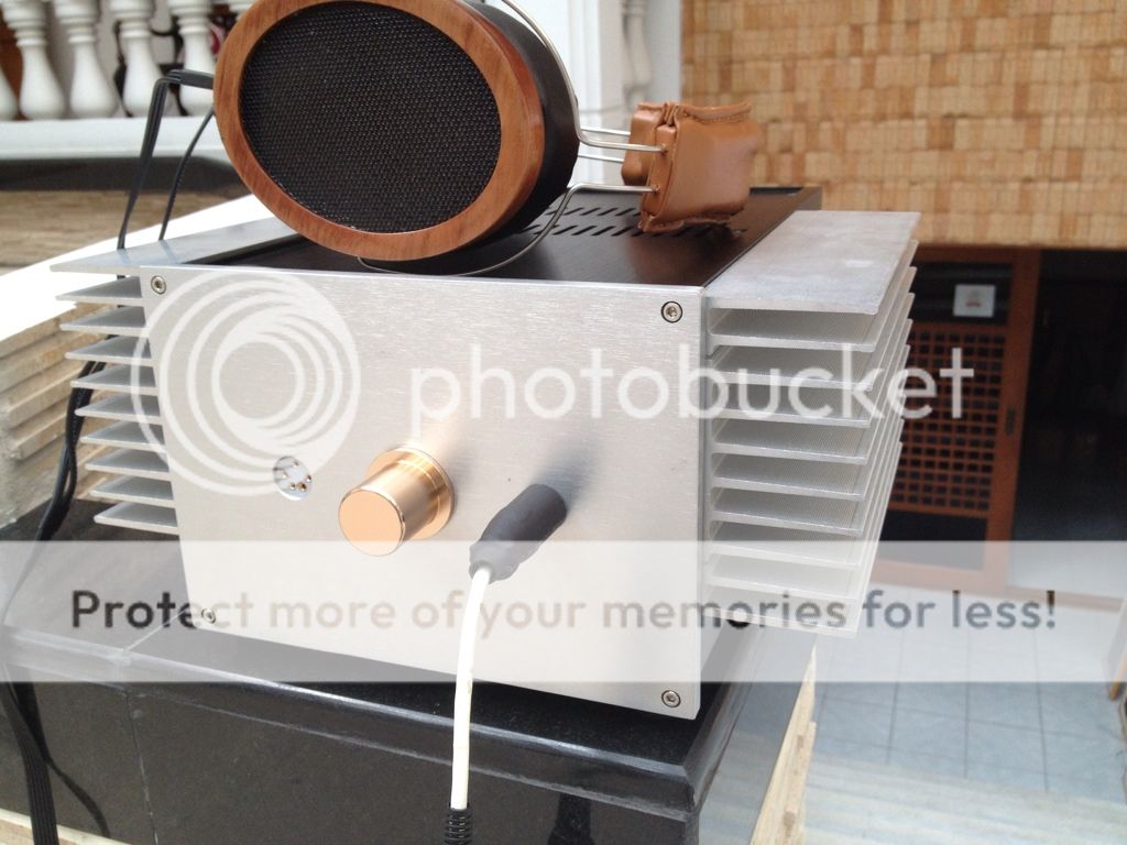
The SRD-5 and SR-3 that I got at a good price from ebay arrived today and I am pleasantly surprised how well they work in their original state. From what I have learnt already I can without doubt improve the SRD-5, and it should immediately have its capacitors replaced as although they don't do much work, and will have little effect on the sound, but they are older than me and could blow at any time.
Interestingly my SRD5 is multi voltage supporting 110 V and 240 V AC, most of the links I have seen on the web show only 110 V operation.
Interestingly my SRD5 is multi voltage supporting 110 V and 240 V AC, most of the links I have seen on the web show only 110 V operation.
impedance Stax transformer
I found another old measurement back 🙂
Impedance is very important for a esl(headhone) transformer. It makes the difference between good sound or not good sound and also easy to drive or difficult to drive.
I found another old measurement back 🙂
Impedance is very important for a esl(headhone) transformer. It makes the difference between good sound or not good sound and also easy to drive or difficult to drive.
An externally hosted image should be here but it was not working when we last tested it.
I found another old measurement back 🙂
Impedance is very important for a esl(headhone) transformer. It makes the difference between good sound or not good sound and also easy to drive or difficult to drive.
Thankyou very much esltransformer, that does like like an easier load than I would have expected. I feared an impedance curve similar to the Quad ESL 57 with nasty low impedance dips.
Regards
Owen
Thankyou very much esltransformer, that does like like an easier load than I would have expected. I feared an impedance curve similar to the Quad ESL 57 with nasty low impedance dips.
Regards
Owen
The Stax measure pretty good, only frequency and fase (+ & -) response from my own is better.
Maybe i will develop a new transformer for the Stax soon. I have new HiB (M0) material and my brother has bought a Stax too so if people here are interested i maybe can reduce the research cost.
See here a picture of my transformer:
An externally hosted image should be here but it was not working when we last tested it.
I have a Koss ESP 9, does the driver for Stax responsible for the Koss?
Regards zeoN_Rider
SR-3 and Koss ESP 9 review.
So it looks like you have some nice devices their as these SR3's are very nice, though mine do need some maintenance.
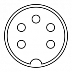
Mine looks like all the pictures of a srd-5 except my plugs and leads and extension lead have what look like higher quality plugs on them, that are definitely not compatible with Stax 5 pin plugs as the it looks to me like a shielded 5 pin din as attached. I expect this is old work, probably before 1980, as I have only seen such solid construction of plugs and sockets on very old equipment. This "upgrade" is exceptionally well done work around for the lack of Stax Sockets, though today I would use a very different design of plugs, and I definitely doubt Shielded DIN plugs are not rated at 230 V RMS. When 5 Pin XLR plugs are rated 125V RMS, or maybe these are an older standard. It might have serial number 9059.
Regards
Owen
Attachments
With all the time effort you'll put into making good transformers, you might want to consider making a good direct drive amp. I really feel that a good direct drive amp sounds much better.
Wachara C.
Wachara C.
I've recently put together a KGSSHV amp designed by Dr. Kevin Gilmore. It sounds really nice with my DIY headphones. 🙂
Wachara C.
Wachara C.
Thank you for explaining "fase", is it be "phase" in english? or is it to do with the delta of phase between positive(+) & negative(-)?The Stax measure pretty good, only frequency and fase (+ & -) response from my own is better.
Maybe i will develop a new transformer for the Stax soon. I have new HiB (M0) material and my brother has bought a Stax too so if people here are interested i maybe can reduce the research cost.
Could you explain a little more your thinking. I look at the board in front of me with 8 transformers all rated 30VA and I look at the little stax transformers and its clear a cheaper transformer solution can be made rather than using 4 large torroidal transformers.
See here a picture of my transformer
Wow its big, I guess you have made a few transformers over the years?
I am also wondering most of all how to do a better than or as good as Stax Headphone driver cheaply. The expensive but definitely good solution is:
SOWTER ELECTROSTATIC LOUDSPEAKER ESL TRANSFORMERS
sowter.co.uk ID : 4342 (or 6504)
Price : £185.44
Power : 50 W
Lowest frequency for full power : 40 Hz
Primary Z ohms: 8
Ratio 1:50 (or 1:70)
Center tapped
Input Volts : 20 (or 14.7)
Output Volts : 1000
but this makes about 400 Euro plus shipping, but it should drive all and any electrostatic headphones beautifully up to the standard of the power signal.
But At around 400 Euros before shipping, it seems a lot of money for the overkill solution, especially if the power is less than 4 Watts Peak, and cost and size of transformers
goes up with power.
I have decided to continue working my 4 per channel step up solution as it is promising, but it is inelegant in bulk.
Because it had no physical structure before it was hard to move.
Moving it onto a board meant everything had to be dismantled, it takes a lot of screwing to do this, all multi core wires are tinned with a soldering iron before attached to the terminal block. I have decided to buffer the transformers with a terminal point per winding and a separate terminal block bringing all the transformers together. this way I can switch between 2,3 and 4 transformers easily without disturbing the rest of the circuit. I guess its almost point to point wiring but bolting terminal blocks to a lump or wood is a lot easier for high voltages and you have no clue what it will look like in the end. Each experiment brings new results.
Regards
Owen
I would definitely have to agree with Wachara on that one.
Your amp is not liking the impedance now and every time you add more transformers you are adding more capacitance.
And upping the transformation ratio only makes it more worse for the amplifier.
I am having this very same issue with my desktop ESL.
My panel little panel has only 50pf of capacitance and the four cores it takes to drive it has nearly 20 times or more as much capacitance and for my very high ratio of well over 1:150 to 1:250 my impedance some where below .3 ohms and .16 ohms at 20khz(as an example).
And I still can't get much below 300hz without running into core saturation problems using the full 40Vrms that my amp can supply.
This also means that only about 5% of the amplifiers power is actually used to create sound out of the panel and the rest of the power is wasted as heat in the transformers dielectric insulating material (at the higher frequency's) and amplifier because of the current it takes to maintain the voltage.
The money you spend on power transformers designed for 60Hz you are better off finding a surplus Tube OPT for P-P 6V6's or something for low power.
That way it will already have enough turns on it for the size of core that it is and still be able to get down to 20Hz or 30Hz with out saturating the core and it should have I decently low amount of capacitance as well to limit the waste of power at the higher frequency's.
Building a Class A P-P solid state amp that can swing 500V tp 1000V p-p is not that hard.
I have made such an amp but only for 200v so far using a dual opamp and a few FET's on my bench using a plug in protoboard.
I did it just to test the methods involved as I used single FET's and FET's stacked up in series (IRF510's) and it worked great.
I have posted my schematics in other threads and have dug up and posted many other versions including the Stax's version that uses the very same topology that I came up with on my own.
A pair of these amps is next on my things to do list only at a much higher voltage of about 3Kv to 5KV instead of 500v for my little ESL's.
Large ESL's would require a much higher current than a smaller panel or even headphones.
Therefore it would be quite dangerous to do for a large panel however it has been done.
And because of the ratio of transformer capacitance vs panel capacitance is shifted to the side of the panels, it is more feasible to use a transformer for a large ESL.
Also with the larger surface area it doesn't have to be driven as hard as a smaller one such as my desktop version to get to the same SPL level.
To compensate for this I have had to use 2X to 4X the bias voltage (10Kv) and 4X the transformation ratio (close to 1:300) than I would have to use for a larger panel that has 8X the surface area.
A good Headphone amp could run on no more than about 300v to 900v.
Just like the old tube circuits.
As for smaller drivers it would be quite feasible and A bit cheaper to do as well as having a better quality signal to drive them with..
I am glad that you are learning about transformers as it is a lot to try to soak in all at once.
I can assure you that it took me quite a while myself and I have been pounding my brain for the better part of the last three years learning about them!!! He,he,he,he 🙂
And it all started here,
http://www.diyaudio.com/forums/planars-exotics/158115-material-esl-3.html#post2082401
http://www.diyaudio.com/forums/planars-exotics/158115-material-esl-3.html#post2082490
http://www.diyaudio.com/forums/planars-exotics/161485-step-up-transformer-design.html#post2093314
here are my findings in a nutshell,
http://www.diyaudio.com/forums/planars-exotics/181041-my-2-nd-esl-attempt-2.html#post2520508
And I am still learning !!!
Cheers!!!!

jer 🙂
Your amp is not liking the impedance now and every time you add more transformers you are adding more capacitance.
And upping the transformation ratio only makes it more worse for the amplifier.
I am having this very same issue with my desktop ESL.
My panel little panel has only 50pf of capacitance and the four cores it takes to drive it has nearly 20 times or more as much capacitance and for my very high ratio of well over 1:150 to 1:250 my impedance some where below .3 ohms and .16 ohms at 20khz(as an example).
And I still can't get much below 300hz without running into core saturation problems using the full 40Vrms that my amp can supply.
This also means that only about 5% of the amplifiers power is actually used to create sound out of the panel and the rest of the power is wasted as heat in the transformers dielectric insulating material (at the higher frequency's) and amplifier because of the current it takes to maintain the voltage.
The money you spend on power transformers designed for 60Hz you are better off finding a surplus Tube OPT for P-P 6V6's or something for low power.
That way it will already have enough turns on it for the size of core that it is and still be able to get down to 20Hz or 30Hz with out saturating the core and it should have I decently low amount of capacitance as well to limit the waste of power at the higher frequency's.
Building a Class A P-P solid state amp that can swing 500V tp 1000V p-p is not that hard.
I have made such an amp but only for 200v so far using a dual opamp and a few FET's on my bench using a plug in protoboard.
I did it just to test the methods involved as I used single FET's and FET's stacked up in series (IRF510's) and it worked great.
I have posted my schematics in other threads and have dug up and posted many other versions including the Stax's version that uses the very same topology that I came up with on my own.
A pair of these amps is next on my things to do list only at a much higher voltage of about 3Kv to 5KV instead of 500v for my little ESL's.
Large ESL's would require a much higher current than a smaller panel or even headphones.
Therefore it would be quite dangerous to do for a large panel however it has been done.
And because of the ratio of transformer capacitance vs panel capacitance is shifted to the side of the panels, it is more feasible to use a transformer for a large ESL.
Also with the larger surface area it doesn't have to be driven as hard as a smaller one such as my desktop version to get to the same SPL level.
To compensate for this I have had to use 2X to 4X the bias voltage (10Kv) and 4X the transformation ratio (close to 1:300) than I would have to use for a larger panel that has 8X the surface area.
A good Headphone amp could run on no more than about 300v to 900v.
Just like the old tube circuits.
As for smaller drivers it would be quite feasible and A bit cheaper to do as well as having a better quality signal to drive them with..
I am glad that you are learning about transformers as it is a lot to try to soak in all at once.
I can assure you that it took me quite a while myself and I have been pounding my brain for the better part of the last three years learning about them!!! He,he,he,he 🙂
And it all started here,
http://www.diyaudio.com/forums/planars-exotics/158115-material-esl-3.html#post2082401
http://www.diyaudio.com/forums/planars-exotics/158115-material-esl-3.html#post2082490
http://www.diyaudio.com/forums/planars-exotics/161485-step-up-transformer-design.html#post2093314
here are my findings in a nutshell,
http://www.diyaudio.com/forums/planars-exotics/181041-my-2-nd-esl-attempt-2.html#post2520508
And I am still learning !!!
Cheers!!!!
jer 🙂
I don't remember what thread I posted the Stax's schematic in but here are some links to some drive circuits and info for a start.
http://www.diyaudio.com/forums/head...ectrostatic-headphone-issues.html#post3213824
http://www.diyaudio.com/forums/planars-exotics/221050-looking-hv-fets-direct-drive.html#post3240864
http://www.diyaudio.com/forums/planars-exotics/80714-another-direct-drive-thread.html#post945897
jer 🙂
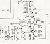
I found the file !!!
http://www.diyaudio.com/forums/head...ectrostatic-headphone-issues.html#post3213824
http://www.diyaudio.com/forums/planars-exotics/221050-looking-hv-fets-direct-drive.html#post3240864
http://www.diyaudio.com/forums/planars-exotics/80714-another-direct-drive-thread.html#post945897
jer 🙂
I found the file !!!
Attachments
Last edited:
In my opinion there is only 1 thing very very importand for a esl transformer: IMPEDANCE
If you have controle over the impedance then the rest will follow as well.
Ohh sorry for "fase" and "phase" . I am a Dutchman....
And here some measurements from an old Sowter transformer i measured in the past.
If you have controle over the impedance then the rest will follow as well.
Ohh sorry for "fase" and "phase" . I am a Dutchman....
And here some measurements from an old Sowter transformer i measured in the past.
An externally hosted image should be here but it was not working when we last tested it.
An externally hosted image should be here but it was not working when we last tested it.
With all the time effort you'll put into making good transformers, you might want to consider making a good direct drive amp. I really feel that a good direct drive amp sounds much better.
Wachara C.
Thank you Wachara, This is very much my fall back plan, and to be quiet honest without ESLtrasnformer's input I would never have considered the solution of making transformers as I know its rather involved, potentially expensive and difficult to change when you decide too.
Until I have an idea of the power and voltage I need to drive these headphones from my own measurements I wont be making any final conclusions or changes of direction. Then depending on sound I may follow a similar path if I am unsatisfied with the power transformers driving the signal. I must say the solution does sound good already, just not finished, and I suspect I have a high frequency resonance issue and need to look into damping.
I am very pleased this went well, I am a little hesitant but must admit from my web search this was one of the designs I liked. I am particularly keen on the use of high voltage NPN rather than FET as I have heard the FET's get less linear with higher voltage, and the capacitance can come to dominate their behaviour, I'm not sure how extreme this is though, as lots of stuff on the web about electronics and HiFi is just rubbish, and building high voltage FET solutions seems to have a lot more suitable devices than with bipolar NPN.I've recently put together a KGSSHV amp designed by Dr. Kevin Gilmore. It sounds really nice with my DIY headphones. 🙂
You are probably right about using a valve/tube output transformer being the best cheap option for good sound. This said I have the transformers, and depending on the tests results will decide if I buy some more transformers for the next experiment, as they will get used one day even if I go for a different solution.The money you spend on power transformers designed for 60Hz you are better off finding a surplus Tube OPT for P-P 6V6's or something for low power.
Building a Class A P-P solid state amp that can swing 500V tp 1000V p-p is not that hard.
I have made such an amp but only for 200v so far using a dual opamp and a few FET's on my bench using a plug in protoboard.
I did it just to test the methods involved as I used single FET's and FET's stacked up in series (IRF510's) and it worked great.
This is interesting, and definitely using transistors or tubes with direct drive is a very goods option but a couple of issues worry me.
1) The power supplies will require regulated high voltages of the type that kills so more complexity at the lethal level.
2) Long term availability of high voltage transistors. I am not yet convinced that we will have many left soon, as Cathode Ray tubes, the last tubes/valves in consumer electronics are almost obsolete, meaning that high voltage transistors are hard to find today and might be impossible soon. For example I could not source KGSSHV parts from my normal suppliers.
A good Headphone amp could run on no more than about 300v to 900v.
Just like the old tube circuits.
As for smaller drivers it would be quite feasible and A bit cheaper to do as well as having a better quality signal to drive them with..
I do tend to agree, transformers are not wonderful things but they do block DC on the stators and do isolate the inputs from the Bias on them and also as an extra benefit provide a phase split, the good sound coming from the tiny Stax transformers in the SRD-5 shows that transformers can be a good and economic solution. Depending on power results I may find inter stage transformers that some other projects have used for driving output, as a 1:6 step up ratio on 100 V amplifier might give headroom and keep the rest of the driver below lethal voltages.
I will follow the transformer drive solution further as I know in time I will use any power transformers in other projects, it is a compromise and we will see what results I get, all have been interesting so fare,
I would like to keep the final build costs for materials below 100 Euro for stereo but I will allow for higher R&D costs, especially if the components can be reused.
I would be very interested to hear other peoples measurements on current and voltage drive on Stax headphone models, and costs of building various solutions. I would also be interested to hear what problems people have with their solutions. For example the last transformer version driving the Stax Lambda Pro's I have built is a too sensitive to the position of the cable, a problem the SRD-5 and SR3 do not suffer from, I suspect this is due to the resonance damping in the SRD-5 and a series resistor might help.
Regards
Owen
Thank you Wachara, This is very much my fall back plan, and to be quiet honest without ESLtrasnformer's input I would never have considered the solution of making transformers as I know its rather involved, potentially expensive and difficult to change when you decide too.
Until I have an idea of the power and voltage I need to drive these headphones from my own measurements I wont be making any final conclusions or changes of direction. Then depending on sound I may follow a similar path if I am unsatisfied with the power transformers driving the signal. I must say the solution does sound good already, just not finished, and I suspect I have a high frequency resonance issue and need to look into damping.
I am very pleased this went well, I am a little hesitant but must admit from my web search this was one of the designs I liked. I am particularly keen on the use of high voltage NPN rather than FET as I have heard the FET's get less linear with higher voltage, and the capacitance can come to dominate their behaviour, I'm not sure how extreme this is though, as lots of stuff on the web about electronics and HiFi is just rubbish, and building high voltage FET solutions seems to have a lot more suitable devices than with bipolar NPN.
You are probably right about using a valve/tube output transformer being the best cheap option for good sound. This said I have the transformers, and depending on the tests results will decide if I buy some more transformers for the next experiment, as they will get used one day even if I go for a different solution.
This is interesting, and definitely using transistors or tubes with direct drive is a very goods option but a couple of issues worry me.
1) The power supplies will require regulated high voltages of the type that kills so more complexity at the lethal level.
2) Long term availability of high voltage transistors. I am not yet convinced that we will have many left soon, as Cathode Ray tubes, the last tubes/valves in consumer electronics are almost obsolete, meaning that high voltage transistors are hard to find today and might be impossible soon. For example I could not source KGSSHV parts from my normal suppliers.
I do tend to agree, transformers are not wonderful things but they do block DC on the stators and do isolate the inputs from the Bias on them and also as an extra benefit provide a phase split, the good sound coming from the tiny Stax transformers in the SRD-5 shows that transformers can be a good and economic solution. Depending on power results I may find inter stage transformers that some other projects have used for driving output, as a 1:6 step up ratio on 100 V amplifier might give headroom and keep the rest of the driver below lethal voltages.
I will follow the transformer drive solution further as I know in time I will use any power transformers in other projects, it is a compromise and we will see what results I get, all have been interesting so fare,
I would like to keep the final build costs for materials below 100 Euro for stereo but I will allow for higher R&D costs, especially if the components can be reused.
I would be very interested to hear other peoples measurements on current and voltage drive on Stax headphone models, and costs of building various solutions. I would also be interested to hear what problems people have with their solutions. For example the last transformer version driving the Stax Lambda Pro's I have built is a too sensitive to the position of the cable, a problem the SRD-5 and SR3 do not suffer from, I suspect this is due to the resonance damping in the SRD-5 and a series resistor might help.
Regards
Owen
If proper designed transformer are wonderfull. You should not do trial&error to find the best normal (toridial)transformer of the shelf nor use tube output transformers unless you have no money to spend.
Ok, good transformers are difficult to find and not cheap but €200,- for a couple (=stereo) transformers is possible.
I expect you are correct.If proper designed transformer are wonderfull. You should not do trial&error to find the best normal (toridial)transformer of the shelf nor use tube output transformers unless you have no money to spend.
The first requirement for me was getting sound out at zero cost, (in the end 15 Euro) and now looking at results I got being surprisingly good considering a 1:20 step up ratio, little optimization seems worth while, and at least a step up ratio of 1:40 might resolve the issues.
The cheapest option is defiantly ebay for the original Stax driver electronics and improving them.
This said money is not a huge issue but gaining experience and measurement is the main objective in the short term.
Ok, good transformers are difficult to find and not cheap but €200,- for a couple (=stereo) transformers is possible.
This I can believe as I think the prices for sowter.co.uk transformers ID : 4342 or 6504 seems prohibitively high. Assuming the 200 Euro for a stereo good transformers, I can guess the performance will be excellent.
I will see very soon how the 4 transformers sound with a step up ratio of 1:40 as it costs me nothing but a little time and care, and also I have far to many audio amplifiers around the house, but some which will go to ebay one day.
regards Owen
Regards
Owen
I don't remember what thread I posted the Stax's schematic in but here are some links to some drive circuits and info for a start.
Thank you these links, they are interesting, and please don't think that because I continue down this path that I am dismissing direct drive.
For a direct drive system, I guess the power supply without custom/valve/tube transformers, one will need 4 normal mains transformers, one to step down for the low tension circuit, and three in series to step up for the shared high tension power supply. For duel power supplies its still going to need 8 mains transformers though the quality of these transformers should have no effect on the sound if within their specified limits.
I may look into building one or more of these circuits later and see if they improve on the basic transformer solution. At this stage I am still attaching wires to all the transformers that are now mounted and the primaries and secondaries attached to terminal blocks. Step by step, little by little this little step up system is coming together.
Thanks everyone,
Owen
- Status
- Not open for further replies.
- Home
- Loudspeakers
- Planars & Exotics
- Making an electrostatic headphone driver.