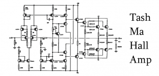
this project is characterized by a high circulating current
especially in the differential input stage
in fact is a current mirror CFP
the next stage is characterized by a bootstrap titpico schema Jeff Rowland
Then the typical triplet EF emitter follower
if you like to use the simulator calculates the optimized values of 35V dual
Thanks😀
especially in the differential input stage
in fact is a current mirror CFP
the next stage is characterized by a bootstrap titpico schema Jeff Rowland
Then the typical triplet EF emitter follower
if you like to use the simulator calculates the optimized values of 35V dual
Thanks😀
Attachments
I don't see the point of the two PNP transistors in the collectors of the input diff stage.
The b-e junction is shorted so there will never be collector current...
Why are they there?
The b-e junction is shorted so there will never be collector current...
Why are they there?
The page cannot be found
The page you are looking for might have been removed, had its name changed, or is temporarily unavailable.
No it's not. Look again, you have drawn it incorrectly.
I looked at the Ultimate Supplifier, and it's not correct what You have drawn.
If You have any idea behind that transistor is, I guess more than me is curious on what it is.
If You have any idea behind that transistor is, I guess more than me is curious on what it is.
The C-B of the two transistors are coupled in blocked mode.
There will not flow any current from the collector up to the B-E-joint.
Again, what ais the purpose of the two PNP-transistors on the diff input stages collectors?
There will not flow any current from the collector up to the B-E-joint.
Again, what ais the purpose of the two PNP-transistors on the diff input stages collectors?
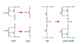
normally in the input stage using transistors with low Ic on the natural bias voltage 0.6 V
this method allows to obtain a driving current of the stadium in tension much wider because the BJT PNP has deliberately characteristics of current@0.6V higher
this method allows to obtain a driving current of the stadium in tension much wider because the BJT PNP has deliberately characteristics of current@0.6V higher
Crossover
I would like to do the speakers for amplifier 60W RMS / 8 ohm. I watched the speakers Woofer Beyma 8BR40/N - 50W RMS, 35 - 6000 Hz, 90 dB, 8 ohm and Tweeter Beyma T2030 - 15W RMS, 1,5 - 20KHz, 95 dB, 8 ohm with crossover Beyma V2 hifi, 300 W, freq 3 KHz, 8ohm.
I turn to you, because I'm not so sure that this is a good relationship and frequency of cutting 3 KHz correct
Would it be better if I would use stronger tweeter and would cut the freq to 4 or 5 KHz
.
Does anybody can help me with advice and calculation for crossover
Best regards
Why are you asking about speaker crossovers in an amplifier forum?
Craig
Probably because I registered for the first time today and I'm still a beginner. Please help me.
Probably because I registered for the first time today and I'm still a beginner. Please help me.
Go to the forums list, Look up the group "Speakers"
There You will find "Multi-Way" as the forum where it would suit fine to post your question.
Start by clinking this link: http://www.diyaudio.com/forums/multi-way/
Last edited:
Now I see what it was supposed to be.
Base connection is in the wrong place in post #1 schematic.
OK, thanks for clarifying your intent.
🙂
Base connection is in the wrong place in post #1 schematic.
OK, thanks for clarifying your intent.
🙂
- Status
- Not open for further replies.
- Home
- Amplifiers
- Solid State
- tash ma hall amp