Hi Abe,
The preamp circuit looks about ready to build, I'd say.
For the Filament's raw dc, please aim for about 6.7Vdc.
Hello Rod,
Here's the model I come up with with your suggestions in mind.
An externally hosted image should be here but it was not working when we last tested it.
Thanks!
Abe
I use AZ1 mesh from 5.6V (220V transformer at 230V), with 1R and 0.5R dropping resistors.One more question, for the AZ1 filament, can I just use 5VCT tap(eg. power transformer) and calculate the dropping resistor to drop 1V at the rectifier current draw? What do you use for your AZ1 filament?
AZ1 filament current varies 1A-1.15A, depends of the manufacturer.
Try 0.5R (5W) on both sides of 5VCT (about 2*0.5V drop), but current must be measured.
Last edited:
I use AZ1 mesh from 5.6V (220V transformer at 230V), with 1R and 0.5R dropping resistors.
AZ1 filament current varies 1A-1.15A, depends of the manufacturer.
Try 0.5R (5W) on both sides of 5VCT (about 2*0.5V drop), but current must be measured.
Thanks much!
Abe
As euro21 says - you can use a 5v winding with two equal resistors on each leg. Start with Ohms Law for measuring the resistor values and then try it out and make whatever changes you need to get exactly 4v. Make sure the resistors are large enough in wattage (again Ohms Law) by sizing them for 3x what they pass. You probably need to parallel a couple of resistors on each leg to get the exact value.
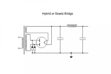
Oh - I should add that if your mains transformer doesn't have a centre tap you need to use a hybrid or Graetz bridge. Diodes can be UF4007 or whatever you fancy.
Attachments
Last edited:
Oh - I should add that if your mains transformer doesn't have a centre tap you need to use a hybrid or Graetz bridge. Diodes can be UF4007 or whatever you fancy.
Excellent. Thanks much Andy!
My #26 is undergoing
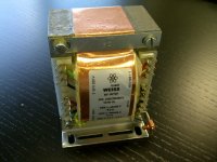
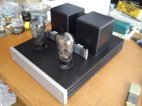
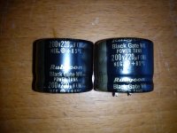
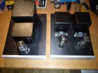
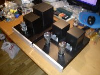
Just received these beauties, more photos of the construction will be posted afterwards.
Thanks Thomas for the Iron (Vinyl Savor)
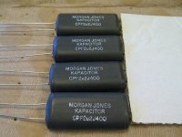
Thanks Campbell Barker for the custom made Morgan Jones capacitors (Supression Devices UK)
Just received these beauties, more photos of the construction will be posted afterwards.
Thanks Thomas for the Iron (Vinyl Savor)
Thanks Campbell Barker for the custom made Morgan Jones capacitors (Supression Devices UK)
Attachments
Last edited:
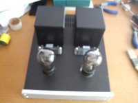
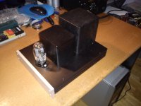
It looks like you made a crucial design change in the mechanical orientation of the filament resistors. 😎
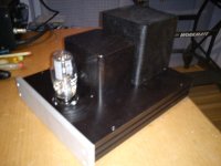
Work in progress
What's the name of that resistors? Where did you get it?
Thanks!
Abe
must be the dales andy recommended
http://www.ebay.co.uk/itm/Resistor-10-Ohms-20-Watts-Dale-HLM-20-10Z-20-pieces-/370292542068
http://www.ebay.co.uk/itm/Resistor-10-Ohms-20-Watts-Dale-HLM-20-10Z-20-pieces-/370292542068
Dale HLM-20-10Z (10 ohms, 20W), NOS ebay 😉What's the name of that resistors? Where did you get it?
Dale HLM-20-10Z (10 ohms, 20W), NOS ebay 😉
The resistors are a present of Massimo🙂
Yup! 😀must be the dales andy recommended
Resistor 10 Ohms 20 Watts Dale HLM-20-10Z (20 pieces) | eBay


Great work Felipe, looking really good!
As a suggestion, you may want to consider increasing the space between individual resistors of each stack as they will get hot. Not the most efficient way to dissipate the heat by stacking them up vertically. I have them just like you buy added some metal separators between them an longer screws...
Ale
- Home
- Amplifiers
- Tubes / Valves
- #26 pre amp