Not questioning H2 cancellation, which is not that easy to achieve in practice. I was just using empirical data to demonstrate that actually 4P1L is more linear than 6C4C.
Ale
Ale
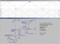
This is what I am coming up with for a 2W all DHT 4P1L headamp, I think it is worth the cost to try and build (FYI there is more 2H going in the output tube than coming out.)
I am not showing the input transformer. Any feedback appreciated. My design decision is coming down to either this SET or a 4P1L + SS Buffer hybrid.

Any chance of posting the screenshot with a better resolution?
I wouldn't run the 4P1L at 325mA filaments as H3 increases significantly and linearity goes down the toilet when swinging large signals. 350/360mA in my experience is the minimum...
Ale
Not questioning H2 cancellation, which is not that easy to achieve in practice. I was just using empirical data to demonstrate that actually 4P1L is more linear than 6C4C.
Ale
Glad you understand what I was trying to say, I agree in real life its difficult but there is some truth to it.
Ill post bigger screenshots in time, right now still looking at the GU-50 vs 6C4C vs PSE 4P1L for the output.
Back to the 4P1L, thanks for the tip about the filament. I agree that it is inherently more linear than a 6C4C up to a point. For my case where I am driving 2 watts into 38 ohms I need to swing a lot of volts across the primary, almost as many volts as an 8W 300B output. So the 4P1L just may not have a high enough plate voltage to work as an output tube for my 2 watts, but it is looking perfect as a driver. Unfortunately my transformer models are the limiting factor here ( I can't figure out how to model the -0.8dB insertion loss of the LL1623.
I could upload a zip of all my sim files including the LTC program on a file share site and you could start simulating with a few mouse clicks. shoot me a PM if you like.
The output transformers are really the frustrating part of designing an unusual SET headamp, almost need to buy the OPT's first, test them for inductace, loss, DCR, etc then choose your tubes & power supply operating points !
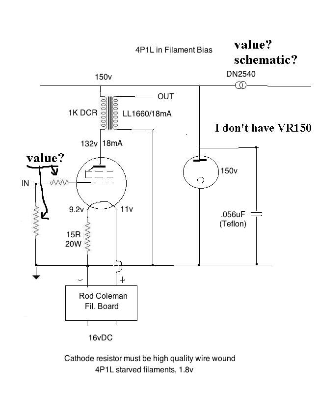
Are you running the 4P1L in series or parallel filaments? Looks like series. I'd run them in parallel at 1.9v. Smaller cathode resistor in filament bias.
Don't neglect to try 4P1L in filament bias on the output. I started with 6C4C with bypassed cathode resistor as you show, and much preferred 4P1L in filament bias. Getting rid of the cathode bypass lifted a veil. In particular the piano sound is incredible, and if you like piano you should hear it.
Don't neglect to try 4P1L in filament bias on the output. I started with 6C4C with bypassed cathode resistor as you show, and much preferred 4P1L in filament bias. Getting rid of the cathode bypass lifted a veil. In particular the piano sound is incredible, and if you like piano you should hear it.
Here's the preamp schematic as requested. Andy
http://www.diyaudio.com/forums/attachments/tubes-valves/319266d1356287761-one-more-4p1l-se-4p1l-ll1660_3.png
Wich values for grid resistor and input to gnd resistor?
Whatever you like in the usual range - maybe 1K grid stopper and 470K to ground. Opinions vary on these things, so I wasn't precise.
Hi Rod,
Building on your idea, here is my first sketch of a 4P1L into 6C4C (or 4P1L PSE). 4P1L driver is using LL1671 IT in filament bias. The fixed grid bias is using your regulator as suggested above. 6C4C/4P1L PSE with output transformer LL1623/60mA. Looks like a good approach. Couldn't simulate it as the ideal current source used in the IT secondary prevents the AC signal to develop in the grid. Any idea of how to overcome this in LTspice?
Thanks
Ale
Hi Ale,
Yes, if the 47K grid resistor is moved to connect across the CCS only - then connect one end of the IT secondary to the bias, the other end to the grid. No other connexions at the grid needed.
This way, the grid sees the bias voltage, but the IT winding feels none of the dc current.
With a high quality IT, this will give an excellent solution!
I just noticed that the LTspice model I use for the 4P1L is modeling 2 in parallel, does anyone have a model for a single?
That's what I a using it is actually representing a pair is parallel. Oddly he doesn't give a single model.
Hi Ale,
Yes, if the 47K grid resistor is moved to connect across the CCS only - then connect one end of the IT secondary to the bias, the other end to the grid. No other connexions at the grid needed.
This way, the grid sees the bias voltage, but the IT winding feels none of the dc current.
With a high quality IT, this will give an excellent solution!
Hello Rod,
Sorry my ignorance what's IT?
Hi Felipe,
It's an interstage transformer like the LL1671 used in my diagram
Feliz Navidad!
Ale
It's an interstage transformer like the LL1671 used in my diagram
Feliz Navidad!
Ale
Hi Ale,
Yes, if the 47K grid resistor is moved to connect across the CCS only - then connect one end of the IT secondary to the bias, the other end to the grid. No other connexions at the grid needed.
This way, the grid sees the bias voltage, but the IT winding feels none of the dc current.
With a high quality IT, this will give an excellent solution!
Cheers Rod, should have thought that one myself!
Here is the updated circuit, I think it should perform well and also can be easily tweaked to get the 4P1L output stage with a 20K grid bias resistor only...
Have a great Christmas!
Ale
Attachments
Hi Felipe,
It's an interstage transformer like the LL1671 used in my diagram
Feliz Navidad!
Ale
Thanks Ale,
Merry Christmas to you too.
Felipe
I just got around to doing some measurements of my 4p1l linestage,
20ma thru a single dn2540 and -12.4v @ 600ma using the phonostages 6e5p and 6c45pi's (shunted with 39r) heaters in filiment bias using coleman reg.
pretty happy for a newish project with lots of refinements available.
2nd harmonic at -85 db and 3rd -97
snr outside of the 50hz which i'm struggling to measure due to soundcard issues (noisy pc i think) is-100 to about 2k then -110+ up to the 40k i measured
and the bandwidth is about the same as my 192khz soundcard at half volume.
great tube!
I did some tests using the 4P1L as a driver in filament bias. Linearity is outstanding in triode mode as measured before, but was keen to see the performance in pentode mode. I tweaked my breadboard to run in pentode albeit it wasn't optimal but still got THD=0.58% @ 200Vpp which is really good for a driver!
4P1L Driver Tests | Bartola Valves
4P1L Driver Tests | Bartola Valves
No second ?
Just to throw in a thought after all the earlier discussion of 2nd harmonic and cancellation & which tube is more linear etc etc .
Why would you want to minimise all of the 2nd harmonic ? ;o)
If I had a pre-amp with 2nd harmonic at 70dB down, and one with no measurable 2nd-harmonic, I know which I would prefer !!
No, you don't. Try first.
- Home
- Amplifiers
- Tubes / Valves
- One more 4P1L SE