Hi Henkjan, I like your comments !
xrk971, interesting thoughts, looking forward to hear (and see) more of it.
xrk971, interesting thoughts, looking forward to hear (and see) more of it.
TABAQUBE model
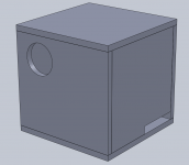
I do not have MJK's model, I am wondering what the effect of all the extra corners would have on the SPL vs frequency? I think corners are treated as area expansions/contractions in the worksheets. So this design would have 6 corners (90 deg turns) with the mean pathlength still the same. Obviously the front baffle is different now so the BSC would have to be modified. I am also considering a way to make the exit port length or width adjustable with a set screw to 'tune' the bass response in real-time. Thanks in advance if anyone is willing to try modeling this before I cut wood.
I do not have MJK's model, I am wondering what the effect of all the extra corners would have on the SPL vs frequency? I think corners are treated as area expansions/contractions in the worksheets. So this design would have 6 corners (90 deg turns) with the mean pathlength still the same. Obviously the front baffle is different now so the BSC would have to be modified. I am also considering a way to make the exit port length or width adjustable with a set screw to 'tune' the bass response in real-time. Thanks in advance if anyone is willing to try modeling this before I cut wood.
in my experience, not a lot (as in the main shape of the curve remains the same), but the main difference can be seen in that in general a folded line gives a smoother response, peaks and dips are lower in amplitudeI do not have MJK's model, I am wondering what the effect of all the extra corners would have on the SPL vs frequency? ....
TABAQUBE as MP3 Portable Speaker?
Less stuffing means louder sound, that is good. I know that these are supposed to give you great imaging of the sound stage because they are point source, what about a crazy application as an mp3 boombox since the shape is cubic and semi-portable? What do you guys think about putting two speakers on this (one will unfortunately, be at about 1/3 the distance to the exit)? Do I have to change the port dimensions? I could put a T-amp inside, have a 3.5mm jack, and add a handle on top. If I made it a little bigger, there could even be room for a Li-ion battery pack and the whole thing becomes portable.
Less stuffing means louder sound, that is good. I know that these are supposed to give you great imaging of the sound stage because they are point source, what about a crazy application as an mp3 boombox since the shape is cubic and semi-portable? What do you guys think about putting two speakers on this (one will unfortunately, be at about 1/3 the distance to the exit)? Do I have to change the port dimensions? I could put a T-amp inside, have a 3.5mm jack, and add a handle on top. If I made it a little bigger, there could even be room for a Li-ion battery pack and the whole thing becomes portable.
Stereo will go to hell in a handback, and interference will also become a problem I predict.
A better bet is probably to do something a bit more elongated like the org. folded TABAQ, to space the drivers a bit more.
A better bet is probably to do something a bit more elongated like the org. folded TABAQ, to space the drivers a bit more.
Hi xrk971
The simulations with MJK´s models does not take into consideration that the cabinet is foldet, you just follow the line ine the middle of the cabinet all the way round.
To be honest I do not know if the folding reduce the need og stuffing. The original stuffing is to level peaks both in the bass and the rest of the frequency.
Your design would probably need a different BSC, whcih I can simulate.
If you are planning to run stereo, however, you could just merge two cabinets into one.
My foldet TABAQ is doing great with New Indeed Klasse T Amp Tripath TA2021
BJohannesen,
I think that corners in MJK's worksheets are implemented as area changes due to cos(theta) effect (see MJK's tutorial at on page 16, http://www.quarter-wave.com/Back_Door/Worksheet_Tutorial_7_03_09.pdf ). When the transmission line is stretched out, it looks like a series of expansions and contractions - and this makes sense that they will serve as low-pass filters. This may be the reason why many back-loaded horn designs work better with lots of 90 degree labyrinth turns rather than smooth curved turns.
Thanks for your great design which has led me to these concepts.
xrk971
How to calculate vent dimensions?
If I want to route the vent to the front instead of going out the side, it will have to pass through a channel at the bottom of one of the front chamber (total passage length is 15.24 cm). The TABAQ currently has a vent port dimension of 1.6 cm x 10 cm in cross section with a length of 9.65 cm. If I want to set the length to exactly 6.0 inches (15.24 cm) in order to match the distance it must travel to make it out the front of the cabinet, how do I solve for the cross-sectional area? In my case, the vent width will be set at 4 in (10 cm), so the gap that is currently at 1.6 cm will probably have to be made greater to deal with the longer vent length. Did you set the length of the vent from the MJK worksheet or can I use something like WinISD and tune it for a bass-reflex cabinet set at 55 Hz?
If I want to route the vent to the front instead of going out the side, it will have to pass through a channel at the bottom of one of the front chamber (total passage length is 15.24 cm). The TABAQ currently has a vent port dimension of 1.6 cm x 10 cm in cross section with a length of 9.65 cm. If I want to set the length to exactly 6.0 inches (15.24 cm) in order to match the distance it must travel to make it out the front of the cabinet, how do I solve for the cross-sectional area? In my case, the vent width will be set at 4 in (10 cm), so the gap that is currently at 1.6 cm will probably have to be made greater to deal with the longer vent length. Did you set the length of the vent from the MJK worksheet or can I use something like WinISD and tune it for a bass-reflex cabinet set at 55 Hz?
The vent is the last part of the line and is simulated by MJK models. Give me a couple of days to re-sim the opening.
Hi xrk791
You are rigth about modelling the corners in MJK model. It will be interesting to fire up MJK models and see the influence on stuffing etc.
Hi from
Bjorn
You are rigth about modelling the corners in MJK model. It will be interesting to fire up MJK models and see the influence on stuffing etc.
Hi from
Bjorn
Hi Bjohannesen,
Thank you for offering to model this for me. The idea of a cube was interesting to me but on thinking about it, aesthetically, I think a slightly taller enclosure would actually look better and give more volume and pathlength for the quarter wave. If I were to make the enclosure 16 in tall, the path could be made 64 in. Additionally, the taller cabinet will force the waves to pass through a longer straight section and prevent some waves from taking the shorter path through the diagonals internal to the cabinet path separators. I think that corresponds to a quarter wave of around 52 Hz? Do you think that would be beneficial?
Thanks again.
Regards,
xrk971
Hi xrk971
I did a test with MJK example and made the model without the increasing / decreasing line caused by the folds.
There is no difference in acoustic impedance, need of damping or the SPL. In other words, is seems the foldings does not change anything.
About the 64 inch line: I need your actual dimensions of the design. but i would expect the tuning would be lower than 52 Hz. TABAQ has a total line of 33,8 inch.
Hi from
Bjorn
Bjorn,
I am surprised that the corners (turns) don't have an effect - it could be that there is so much damping from the stuffing? If you have lots of turns, maybe the effect will be more noticeable? In any event, the dimensions for my design with the 6 corners is attached following MJK's format.
Thank you,
xrk971
Attachments
You won't see the effects of corners in the model. The main effect of sharp corners is to create a low-pass filter. I.e., higher frequency harmonics etc doesn't go around the corners. This is why smooth, flowing bends in TL's and backhorns are not a good idea. The smooth bends look pretty, but they allow a lot of unwanted junk to pass through to the terminus.
Bob
Bob
Bob,
I agree that the corner should act as low pass filters. If it doesn't show up in the results of the model, what is the point of providing the model with this level of detail? There must be a way that it shows up somewhere, otherwise how do we use the model to design new TL's and horns? Would the impedance curve of the output at the terminus only show high value for higher frequencies?
xrk971
Bob,
I agree that the corner should act as low pass filters. If it doesn't show up in the results of the model, what is the point of providing the model with this level of detail? There must be a way that it shows up somewhere, otherwise how do we use the model to design new TL's and horns? Would the impedance curve of the output at the terminus only show high value for higher frequencies?
xrk971
First. I do TL's, not horns, but still....
Look at the output from HornResp. Do real, made in wood horns really sound that bad? Of course not! The models only reflect a single dimension -- the length of the pipe/horn. Once the sound waves starts bouncing around in three dimensions, things smooth out. I think that you are expecting too much from the models. The models are excellent at predicting the high pass cutoff, pretty good at predicting the first two or three overtones, and beyond that, provide a general indicator of what to expect. For mid-bass horns -- F3 60hz or so or TL's to 40Hz or so, don't expect much guidance above 500Hz.
I find that the impedance plot is only an indicator that something is happening. If there is a discontinuity, look at the frequence of time plots.
Bob
has anyone got comparative data plots comparing the same basic horn length, mouth+throat but one with a standard curved horn VS a folded/manifold style line?
difference in output frequency from the terminus between them?
I was planning on doing this between my failed BiB style curved horn VS basically the same horn design but used in a manifold set-up; but the data etc for the first failed attempt was lost when my laptop died.
difference in output frequency from the terminus between them?
I was planning on doing this between my failed BiB style curved horn VS basically the same horn design but used in a manifold set-up; but the data etc for the first failed attempt was lost when my laptop died.
Hi xrk791
First: I do like that MJK is using Sd to set cross section, it makes it easy to change volume. I normally start with a cross section 3 times Sd and simulate frome there, trying different parameters along the way. This is very fun, by the way, and you get the feeling of quarter wave design.
I have simulated your design, with the last 6 inches with a cross section of 1 sd = 32 cm2.
The enclosure has a tuning frequency of about 38 Hz, which is much too low for this driver. I would suggest the folds to have a total line of 30 inch (plus the last narrow part), as in TABAQ.
Hi from
Bjorn
- Home
- Loudspeakers
- Full Range
- TABAQ TL for Tangband