the battery voltage drop is not such a big deal, I cut my A123 higher than that though, my circuit cuts at 3.15, theres not much left after that anyway, drop is pretty fast from 3.15-3, about as quick as the initial drop from 3.6-3.45vdc.
I have to say, much as I like that new LDO; it looks great and good current capability, but how about making a small flexible low noise reg that others could use in various positions? using your layout skills, which are considerable as we know, a small high performance flea type reg could be realised.
basically a buffered flea type, a higher current version of Ackos regs. I have been using something like this for my clock, made from a ltc6655 reference + LCR filter feeding one of opc's SE-SE 'the wire' headphone amps which is made from LME49990 + LME49600.
it needs a bipolar supply unless its an isolated load, so not at all efficient in that way, not low dropout, but copes with power up to +/-18V for even 1.2v output. Most will have a bipolar supply somewhere in the case to power it with.
What you end up with is VERY low noise across a wide bandwidth and will do 250mA without a heatsink apart from the PCB at low voltages
with this we are down in the nV range, not sure exactly what noise but pretty darn low, much less than 1µV with the right LCR filter, probably less than 500nV and maybe much less. ive been playing with some ideas for a layout of my own, i've been just using a separate reference circuit feeding one of the cheap SE-SE boards that had an error Owen was selling, but something small and neat will be better.
Si570 interest list:
1. bigpandahk
2. tagheuer
3. hochopeper
4. qusp (of course)
5. AR2 - definitely!
6. wktk_smile
7. hirez69
8. CeeVee - you bet!
9. number9
10. analog_sa - GB maniac
11. edbk
12. atom6422
13. misterrogers - Of Course!
14. NicMac - as usual!
1. bigpandahk
2. tagheuer
3. hochopeper
4. qusp (of course)
5. AR2 - definitely!
6. wktk_smile
7. hirez69
8. CeeVee - you bet!
9. number9
10. analog_sa - GB maniac
11. edbk
12. atom6422
13. misterrogers - Of Course!
14. NicMac - as usual!
1. bigpandahk
2. tagheuer
3. hochopeper
4. qusp (of course)
5. AR2 - definitely!
6. wktk_smile
7. hirez69
8. CeeVee - you bet!
9. number9
10. analog_sa - GB maniac
11. edbk
12. atom6422
13. misterrogers - Of Course!
14. NicMac - as usual!
15. Zoran
2. tagheuer
3. hochopeper
4. qusp (of course)
5. AR2 - definitely!
6. wktk_smile
7. hirez69
8. CeeVee - you bet!
9. number9
10. analog_sa - GB maniac
11. edbk
12. atom6422
13. misterrogers - Of Course!
14. NicMac - as usual!
15. Zoran
Si570 interest list:
1. bigpandahk
2. tagheuer
3. hochopeper
4. qusp (of course)
5. AR2 - definitely!
6. wktk_smile
7. hirez69
8. CeeVee - you bet!
9. number9
10. analog_sa - GB maniac
11. edbk
12. atom6422
13. misterrogers - Of Course!
14. PET-240
1. bigpandahk
2. tagheuer
3. hochopeper
4. qusp (of course)
5. AR2 - definitely!
6. wktk_smile
7. hirez69
8. CeeVee - you bet!
9. number9
10. analog_sa - GB maniac
11. edbk
12. atom6422
13. misterrogers - Of Course!
14. PET-240
Fixed it for you Drew 😉
Si570 interest list
1. bigpandahk
2. tagheuer
3. hochopeper
4. qusp (of course)
5. AR2 - definitely!
6. wktk_smile
7. hirez69
8. CeeVee - you bet!
9. number9
10. analog_sa - GB maniac
11. edbk
12. atom6422
13. misterrogers - Of Course!
14. NicMac - as usual!
15. Zoran
16. PET-240
Si570 interest list
1. bigpandahk
2. tagheuer
3. hochopeper
4. qusp (of course)
5. AR2 - definitely!
6. wktk_smile
7. hirez69
8. CeeVee - you bet!
9. number9
10. analog_sa - GB maniac
11. edbk
12. atom6422
13. misterrogers - Of Course!
14. NicMac - as usual!
15. Zoran
16. PET-240
Sorry, was not fOllowing this for some time, I don't see any price on this, any idea? Anyway put my name in first, don't want to miss the good thing.
Si570 interest list
1. bigpandahk
2. tagheuer
3. hochopeper
4. qusp (of course)
5. AR2 - definitely!
6. wktk_smile
7. hirez69
8. CeeVee - you bet!
9. number9
10. analog_sa - GB maniac
11. edbk
12. atom6422
13. misterrogers - Of Course!
14. NicMac - as usual!
15. Zoran
16. PET-240
17. Coolhead
Si570 interest list
1. bigpandahk
2. tagheuer
3. hochopeper
4. qusp (of course)
5. AR2 - definitely!
6. wktk_smile
7. hirez69
8. CeeVee - you bet!
9. number9
10. analog_sa - GB maniac
11. edbk
12. atom6422
13. misterrogers - Of Course!
14. NicMac - as usual!
15. Zoran
16. PET-240
17. Coolhead
no, dont know price, but given Ians modules are usually effectively charity I dont think its anything to stress about...
Wow, quite a lot of upgrades, don't know should I mail back my old board (first version) for upgrade or should get get a new one, any suggestion?
I am definitely interested in the battery control board, need to look at more post to see what is needed to do in a single shipment.
Thanks you.
I am definitely interested in the battery control board, need to look at more post to see what is needed to do in a single shipment.
Thanks you.
the isolator is not yet available, only 10 prototypes were sent out for testing, mine arrived today and looks good! It came complete with complementary resistor networks, Ian's generosity and productivity seems limitless! the battery board is again in prototype stage and none of these are upgrades, but separate modules so there would be no point sending it back unless you want the firmware upgraded
What version of firmware is required for si570 board?
Both V3.3x and V3.8x are OK. But if you want all the new features, the latest version is safer.
Ian
Thanks!
1. bigpandahk
2. tagheuer
3. hochopeper
4. qusp (of course)
5. AR2 - definitely!
6. wktk_smile
7. hirez69
8. CeeVee - you bet!
9. number9
10. analog_sa - GB maniac
11. edbk
12. atom6422
13. misterrogers - Of Course!
14. NicMac - as usual!
15. Zoran
16. PET-240
17. Coolhead
18. Slartibartfasst
1. bigpandahk
2. tagheuer
3. hochopeper
4. qusp (of course)
5. AR2 - definitely!
6. wktk_smile
7. hirez69
8. CeeVee - you bet!
9. number9
10. analog_sa - GB maniac
11. edbk
12. atom6422
13. misterrogers - Of Course!
14. NicMac - as usual!
15. Zoran
16. PET-240
17. Coolhead
18. Slartibartfasst
the battery voltage drop is not such a big deal, I cut my A123 higher than that though, my circuit cuts at 3.15, theres not much left after that anyway, drop is pretty fast from 3.15-3, about as quick as the initial drop from 3.6-3.45vdc.
I have to say, much as I like that new LDO; it looks great and good current capability, but how about making a small flexible low noise reg that others could use in various positions? using your layout skills, which are considerable as we know, a small high performance flea type reg could be realised.
basically a buffered flea type, a higher current version of Ackos regs. I have been using something like this for my clock, made from a ltc6655 reference + LCR filter feeding one of opc's SE-SE 'the wire' headphone amps which is made from LME49990 + LME49600.
it needs a bipolar supply unless its an isolated load, so not at all efficient in that way, not low dropout, but copes with power up to +/-18V for even 1.2v output. Most will have a bipolar supply somewhere in the case to power it with.
What you end up with is VERY low noise across a wide bandwidth and will do 250mA without a heatsink apart from the PCB at low voltages
with this we are down in the nV range, not sure exactly what noise but pretty darn low, much less than 1µV with the right LCR filter, probably less than 500nV and maybe much less. ive been playing with some ideas for a layout of my own, i've been just using a separate reference circuit feeding one of the cheap SE-SE boards that had an error Owen was selling, but something small and neat will be better.
Kelvin connection and grounding layout are the key things for this reg to keep the low noise performance I think. Will see how it gonna be once get the PCB.
TPS7A4700 is a bipolar LDO, so XOs is supposed to be gain from it's low 1/f noise comparing with CMOS. Output programmable by jumpers. The whole PCB will be the heat sink.
Please give me a bit more details about the reg you mentioned.
BTW, for a AC based PSU, it will gain from LCR filter, however, for a battery based PUS, the L will increase noise at some frequencies point. I'm trying avoid using any L in my very low noise application now, such as a XO stage. What's your expericnce on the LCR filter? multi-stage?
Thanks
Ian
Last edited:
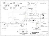
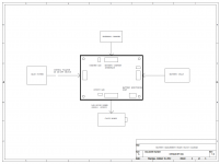
Schematics and BOM of the passive battery management board
The passive battery management board is approved functional. I know it’s one of the best solutions providing clean battery based power for isolated clock board and DAC. So I decide to list it on the next GB.
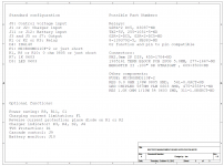
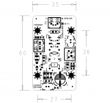
Here I attached the schematics, BOM and PCB silk screen. The principle and schematic are very simple, I don’t think I need making any note on it. Beside the standard configuration, there are a lot of optional functions, but you have to figure out by yourself.
In order to make sure everything is OK before the GB, I’d like to provide 10 free PCB samples for evaluation. To save time for both of us, please list your ID on the list below by yourself if you decide to apply, and then at same time, send me an email at iancanada.mail@gmail.com with your apply number, diyAudio ID and shipping address. PCB will be shipped next week. Apply will be closed if 10 names on the list already. Please let us know your testing result.
Thanks
Ian
The passive battery management board is approved functional. I know it’s one of the best solutions providing clean battery based power for isolated clock board and DAC. So I decide to list it on the next GB.
Here I attached the schematics, BOM and PCB silk screen. The principle and schematic are very simple, I don’t think I need making any note on it. Beside the standard configuration, there are a lot of optional functions, but you have to figure out by yourself.
In order to make sure everything is OK before the GB, I’d like to provide 10 free PCB samples for evaluation. To save time for both of us, please list your ID on the list below by yourself if you decide to apply, and then at same time, send me an email at iancanada.mail@gmail.com with your apply number, diyAudio ID and shipping address. PCB will be shipped next week. Apply will be closed if 10 names on the list already. Please let us know your testing result.
Thanks
Ian
Attachments
Testing group list of free evaluation samples of passive battery management board PCB
Please list your ID below by yourself and send me an email with your apply number, diyAudio ID and shipping address at same time. With battery management board free sample on the title of email. Thanks
1. qusp
2.
3.
4.
5.
6.
7.
8.
9.
10.
(Apply will be closed if 10 IDs already on the list)
Please list your ID below by yourself and send me an email with your apply number, diyAudio ID and shipping address at same time. With battery management board free sample on the title of email. Thanks
1. qusp
2.
3.
4.
5.
6.
7.
8.
9.
10.
(Apply will be closed if 10 IDs already on the list)
Last edited:
1. qusp
2. bigpandahk
3.
4.
5.
6.
7.
8.
9.
10.
(Apply will be closed if 10 IDs already on the list)
Battery management PCB testing group list:
1. qusp
2. bigpandahk
3.
4.
5.
6.
7.
8.
9.
10.
( will be closed if 10 IDs already on the list)
Thanks
1. qusp
2. bigpandahk
3.
4.
5.
6.
7.
8.
9.
10.
( will be closed if 10 IDs already on the list)
Thanks
Battery management PCB testing group list:
1. qusp
2. bigpandahk
3. SPWONG
4.
5.
6.
7.
8.
9.
10.
Thanks.
1. qusp
2. bigpandahk
3. SPWONG
4.
5.
6.
7.
8.
9.
10.
Thanks.
Kelvin connection and grounding layout are the key things for this reg to keep the low noise performance I think. Will see how it gonna be once get the PCB.
yeah I use kelvin on my LT regs when I can, well only if there is significant lead length
oh sure, I think it'll be great, one isnt a replacement for the otherTPS7A4700 is a bipolar LDO, so XOs is supposed to be gain from it's low 1/f noise comparing with CMOS. Output programmable by jumpers. The whole PCB will be the heat sink.
Please give me a bit more details about the reg you mentioned.
OK, will email you some details
BTW, for a AC based PSU, it will gain from LCR filter, however, for a battery based PUS, the L will increase noise at some frequencies point. I'm trying avoid using any L in my very low noise application now, such as a XO stage. What's your expericnce on the LCR filter? multi-stage?
yes, combination of series and parallel and i'm also playing with multiloop RC feedback around the opamp for it, thats what I wanted to do with my PCB.
- Home
- Source & Line
- Digital Line Level
- Asynchronous I2S FIFO project, an ultimate weapon to fight the jitter