PEECEEBEE done. Now to order parts. 🙂 Thanks!
😎
nice PEECEEBEE Cambe, like me


results from the pdf file created mirror.
right after they were staying print only 😀 😀
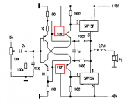
there is a similar with EF output
Stee where did you find that schematic ? Can you identify the amp ?
Anyway thats the good sounding version, class A is the way the amp should be biased other you get the overbright sound mikelm described.
Common Collectors works better
²ÉÓÃSAP15×é³ÉµÄ50W¹¦·Åµç·-ÒôÊÓƵµç·-µç·ͼ´óÈ«-Öйúµç×ÓÍø-µç×Óµç·ͼ|ÔªÆ÷¼þ×ÊÁÏ|µç×ӵ繤µçÁ¦¼¼Êõ
²ÉÓÃSAP15×é³ÉµÄ50W¹¦·Åµç·-ÒôÊÓƵµç·-µç·ͼ´óÈ«-Öйúµç×ÓÍø-µç×Óµç·ͼ|ÔªÆ÷¼þ×ÊÁÏ|µç×ӵ繤µçÁ¦¼¼Êõ
Attachments
nicely done!, but look like you've reversed it.
should look like this http://www.diyaudio.com/forums/solid-state/193923-simple-symetrical-amplifier-309.html#post3171741
If simply reversed, the words "SSA" and "SHAAN" would also look reversed, but not. So, there's human action here.

Erm, SSA and sHAAN would look reversed from the copper side when printed mirrored.
But it's not. And from parts side it looks obvious that it's been etched without mirroring.
Naf manually flipped the SSA and SHAAN so that from the copper side they don't read NAAHS and A**.
But it's not. And from parts side it looks obvious that it's been etched without mirroring.
Naf manually flipped the SSA and SHAAN so that from the copper side they don't read NAAHS and A**.
Hi Stee. Thanks for your kind contribution. We had no idea if it would work better in common collector.
Naf manually flipped the SSA and SHAAN so that from the copper side they don't read NAAHS and A**.
hi shaan, can i supply with +/-45v for SSA ,is there any change
thanks.
I haven't tried it with +-45V but a quick simulation shows the following changes.
1: 470ohm Zener feed resistor increased to 1K.
2: 1K2 Current feed resistor might need to be increased to 1K3. As the higher PS potential causes high current draw in VAS.
3: Removal of one of the 1N4148 diodes and use only one to bias the FETs to about 175mA.
The input bias and VAS bias must be carefully set with varying the 1K2 resistor. You will probably get reduced THD with higher PS voltage. And of course more power into same load.
Hi Shaan,
Thank you, I did the same thing with Version 1.4 PCB post #498. Version 1.4 is corrected now and I have all the parts for it so,I will start on it while awaiting parts and new PCB material for the PEECEEBEE. 🙂
😎
Thank you, I did the same thing with Version 1.4 PCB post #498. Version 1.4 is corrected now and I have all the parts for it so,I will start on it while awaiting parts and new PCB material for the PEECEEBEE. 🙂
😎
okey shaan,coz i have etch the PCB,but my PSU +/- 45v..
thanks
Nice.
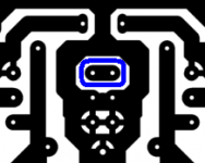
Just a little tip for safety. The single 1N4148 diode's anode goes to the previous upper 1N4148's anode, and the cathode goes to the lower one's cathode. Nothing goes through the two holes inside the blue borders shown in the attachment.
Attachments
 )
) Nice.
Just a little tip for safety. The single 1N4148 diode's anode goes to the previous upper 1N4148's anode, and the cathode goes to the lower one's cathode. Nothing goes through the two holes inside the blue borders shown in the attachment.
ok shan , i will always need you,to finish this amp😀
number 20 of 20 Reasons To Go For SSA 🙂ok shan , i will always need you,to finish this amp😀
Don't you like straps ?
No.
But yes despite looking ugly, they might be useful here.
- Status
- Not open for further replies.
- Home
- Amplifiers
- Solid State
- Simple Symetrical Amplifier