badrisuper, In case you need some help with the AC voltages (I did) please look at this series of posts.
http://www.diyaudio.com/forums/chip...on-beta-build-fine-tuning-14.html#post2962780
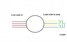
Dario is asking about the label on your transformer because it usually has a diagram of the loops on both the in and out sides of the toroid. They need to be positioned relative to "hot" and "return" on the FE.
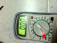
If you don't have a label you can use the continuity mode (see red arrow) of your VOM to sniff out which pair of wires form a loop inside the transformer. This is done with no power (AC) applied.
The attached PDF gives some examples of the loops/circuits you need to determine.
The drawing shows what I think is your trani. Green shows possible loops that need to be determined.
For safety, please remove the toroid from your build while doing these tests. After the information is gathered, power can be applied to determined the output of each toroid.
These are steps we all had to do/learn so please don't feel this is something you should already know. If there is anything you don't know please ask. We all learn together.
http://www.diyaudio.com/forums/chip...on-beta-build-fine-tuning-14.html#post2962780
Dario is asking about the label on your transformer because it usually has a diagram of the loops on both the in and out sides of the toroid. They need to be positioned relative to "hot" and "return" on the FE.
If you don't have a label you can use the continuity mode (see red arrow) of your VOM to sniff out which pair of wires form a loop inside the transformer. This is done with no power (AC) applied.
The attached PDF gives some examples of the loops/circuits you need to determine.
The drawing shows what I think is your trani. Green shows possible loops that need to be determined.
For safety, please remove the toroid from your build while doing these tests. After the information is gathered, power can be applied to determined the output of each toroid.
These are steps we all had to do/learn so please don't feel this is something you should already know. If there is anything you don't know please ask. We all learn together.
Attachments
Last edited:
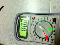
There is a continuity mode with audible beep on your your meter. Green arrow. Using that is a simpler/preferred method. Sorry, a little dense yesterday.
Attachments
Last edited:
There's no label on the transformer?
Possibly you wired it incorrectly.
Regarding sound It could depend on a lot of things... source, burn-in, some component orientation ( did you turned again R11s?) and so on.
First thing is to have two working modules and listen in stereo 😉
Yes Dario, there is no label in the transformer. Now I solved the transformer issue. Now new issue sprouted out. One board is working fine. But in another one, relay is clicking and switching off repeatedly light is on and off repeatedly. I dont know now what is the issue. Yesterday both board were fine, but now today new issue. Any idea?
Thanks
Badri
There is a continuity mode with audible beep on your your meter. Green arrow. Using that is a simpler/preferred method. Sorry, a little dense yesterday.
Thanks bcmbob. I did as you mentioned. New learning. The problem is connectivity issue. Now its solved.
Forgot to mention after I switch off the power, light is glowing atleast for a second. Any suggestion?
Your welcome. That sounds like there is still a voltage problem. Are you sure the wiring from both toroids is identical. It is easy to reverse something when all the leads are the same color. I sometimes use a small piece of heatshrink tube or a magic marker to designate "hot". I have made that mistake a couple times. Reversing the red wires on the input side of the non-working assembly toroid might also be an option.
Last edited:
How I connected for one board, the same way I am connecting for another. But the relay is clicking and switching off repeatedly for one board and for another its working. Shall reverse the wiring? Will it harm the board?
Thanks
Badri
Thanks
Badri
The FE power system is a little tricky and sensitive to the relation of hot and ground on both sides of the transformer from my understanding. It was dealt with a bit on this post, but if you can, please post a simple diagram of the loops/circuits on your toroids. It will be easier to determine. Dario can decipher what's best for the FE if he can see what is there.
I meant reversing only the input side wires, not the leads from toroid to amp. I had a similar problem connecting multiple toroids in an integrated build. Take a look backwards to where both transformers branch from a common feed. Hope that makes sense to you.
I meant reversing only the input side wires, not the leads from toroid to amp. I had a similar problem connecting multiple toroids in an integrated build. Take a look backwards to where both transformers branch from a common feed. Hope that makes sense to you.
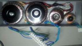
Here is an example. These toroids have both red and black in wires. Easy to tell apart. Yours appear to be all red and can be in the wrong place. I don't know if that is your problem. but the function/polarity of the leads need to be consistent. In the photo all red is to red - all black is to black.
Attachments
Last edited:
Forgot to mention after I switch off the power, light is glowing atleast for a second. Any suggestion?
sounds like I had the same issue! make sure your toroid is connected correctly, check voltage after rectification across PS caps, then check across C102/C202 it should be around 14vdc on both rails, let us know if it's so. If not check R11 if it's shorted.
sounds like I had the same issue! make sure your toroid is connected correctly, check voltage after rectification across PS caps, then check across C102/C202 it should be around 14vdc on both rails, let us know if it's so. If not check R11 if it's shorted.
Thanks dtses. What caused this problem? How did you fix it?
Thanks
Badri
i've cooked R11 for 4-5 times, one of them was likely when I shorted toroid's secondaries. But anyway you should check voltage first of all even if R11 is ok
I connected up my boards one channel at a time with a 50va transformer with 2x20v secs and a light bulb tester to check that things were in the right ballpark and that nothing smoked.The right channel gave the following readings and looks good to go.
C101/201 +- 28.52v
C102/202 + 14.65v - 14.36v
Offset -4.2mv
Left channel
C101/201 +- 27.5v
C102/202 + 14.2v - 14.65v
Offset 1.25v
The input also has about 0.5v on it.
Any pointers/advise would be much appreciated.
C101/201 +- 28.52v
C102/202 + 14.65v - 14.36v
Offset -4.2mv
Left channel
C101/201 +- 27.5v
C102/202 + 14.2v - 14.65v
Offset 1.25v
The input also has about 0.5v on it.
Any pointers/advise would be much appreciated.
Yes I realise that just wondered where to start looking.
I forgot to say that on the faulty channel the relay did not click nor the led light up until I started checking voltages namely the voltages across C102/202.
I forgot to say that on the faulty channel the relay did not click nor the led light up until I started checking voltages namely the voltages across C102/202.
the input will probably not be 0V.
If the DC blocking capacitor has ZERO leakage current then you should see ZERO Volts, if the input has a grounding resistor.
If the DC blocking cap leaks and/or the grounding resistor is omitted, then it is very likely that a non Zero voltage will exist on the input.
If you measure the input after the DC blocking capacitor or omit the DC blocking capacitor then you will measure the input offset voltage of the chipamp.
This input offset can be upto 600mVdc.
output offset ~ 1.2Vdc indicates an error.
I recleaned the pcb's this morning and reflowed a couple of joints that looked a bit iffy and rechecked the voltages.Most values are as shown in previous posts but the offset now reads 3 volts and input .4v.On the good board the input reads 200mv but drops to afew mv's with the dmm left connected across it and the output reads 2.4mv with the input shorted.Have I fried either the 318 or the 3886 or both?Tia for any advice.
Where is the 0.4V coming from at the input?
Is that 0.4V an AC voltage or a DC voltage?
Is it before the DC blocking cap?
Have you used a DC blocking cap?
What type is it?
Is it leaking?
Is that 0.4V an AC voltage or a DC voltage?
Is it before the DC blocking cap?
Have you used a DC blocking cap?
What type is it?
Is it leaking?
Thanks Andrew.The input has a polypropylene connected and the voltage is dc which starts at .26v drops slowly with the dmm connected but then rises back up again.I've just noticed that the heatsink warms up whereas the other channel it stays cold.The relay is slow to latch on and clicks on and off over a few minutes.
Last edited:
When I have had a similar problem there was a short/solder bridge involved. One place to look is between the input pin bracket and the PCB. It can be solder or even a tiny piece of wire caught underneath the plastic pin housing. A failing resistor or one with incorrect value also bit me on a V1.3. That also caused excessive heat at the heat sink.
- Status
- Not open for further replies.
- Home
- Amplifiers
- Chip Amps
- My_Ref Fremen Edition RC - Build thread