OK, do you have a multimeter? if you have one, measure the hfe with it. fine 2 transistor that has same or close hfe, that's the simplest way.
Hi,
so I just ended soldering the JLH boards, wired everything, plugged it in, and.. the fuses burned out..
my configuration:
toroidal transformer with dual 18.6V
the power supply that is suggested on the site, it's output is -25 0 +25
the speakers are 4Ohm (as measured with my multimeter)
the preamp is a tube one, checked with my headphones before so it should be working ok.
the fuses on the power supply, and on one of the JLH boards burned out. I think the front audio panel on my computer burned as well..
i changed the fuses on the power supply and connected the JLH board with intact fuse, and.. the C1 capacitor went smokin'..
any ideas how to debug where the problem might be? one board at a time..
or should i give up DIY and buy a yamaha amp?
You obviously made a mistake somewhere. No pic = no comment. There is no way on earth good advice can be given without seeing the build.
My guess is that you swapped resistors or put transistors in reverse. Or simply a short....
My guess is that you swapped resistors or put transistors in reverse. Or simply a short....
Do NOT connect the speaker before adjust the output to around 0V
ok.. that's one good advice I wasn't aware of.. ok.. I'll give it another try.
everyone, thanks for the replies
I'm running fast out of components..
I've resoldered the board. removed C3 and shorted it as in some previous post. without connecting it to the speakers the output voltage is 25V. tried to play with VR1, VR2, VR3, the output voltage did not change.
any ideas?
I've resoldered the board. removed C3 and shorted it as in some previous post. without connecting it to the speakers the output voltage is 25V. tried to play with VR1, VR2, VR3, the output voltage did not change.
any ideas?
Attachments
if the output is 25V, there must be something wrong: failure parts, unconnected pins, bad transistors, short circuits..you can check the center point voltage stage by stage to find the problems.
I have 4 big toroid transformer which were disassemblyed fron an US made auido equipment, like new. They are 110V and usless for me. I would like to send it to those who want to buy JLH amplifier full kit + Power supply for free
This transformer is ideeeeeeal for Stereo JLH power amplifier (for US and canada DIYers). Spec:
Power: >150W
output1: 24-17-0-17-24
output2: 8V
weight: 2kg
Only 4 available, only one for one person.
Plus $25 for air shipping. PM me if you have interest.
Ray,
You,ve got PM
-Chas
I'm running fast out of components..
I've resoldered the board. removed C3 and shorted it as in some previous post. without connecting it to the speakers the output voltage is 25V. tried to play with VR1, VR2, VR3, the output voltage did not change.
any ideas?
Smaller pictures please. No more than 1200X900.

I'm running fast out of components..
I've resoldered the board. removed C3 and shorted it as in some previous post. without connecting it to the speakers the output voltage is 25V. tried to play with VR1, VR2, VR3, the output voltage did not change.
any ideas?
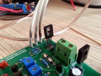
on the first pic, you sure have a blown transistor. and the cables to the output transistor have been very hot.
do you massure 25V on speaker output?
Oh...look at the time, it had been sold before our galaxy formed.
So that was the big bang I heard... 😱
Hard to design a stable amp in an oscillating Universe...🙄
-Chas
Salas, sorry, thought they would be scaled correctly.
AudioSan, yes, the output is 25V. the wires were not hot, it's the smoke from the blown transistor, too bad I didn't record it, it was pretty awesome..
while testing, the input should or should not be connected?
it's my first audio DIY project and I am still struggling to understand how things work.. I'm waiting to get some free time to start debugging it, checking voltages along the way, may be verify the transistor states...
then its no wonder you are massuring 25V at the output🙂
first you need to figgure out why the transistor went to transistor heaven🙂
did it blow rigth away? or did it take some time?
first you need to figgure out why the transistor went to transistor heaven🙂
did it blow rigth away? or did it take some time?
AudioSan, it blew up after I messed arround with VR1. Unfortunately yesterday i shorted the Q3 again (always use goggles) with the test probe, while measuring the voltages , so now I'm out of components for further testing.. but the preliminary tests showed that the voltages for tr1 - tr4 do not have the values (I mean translated to 25V rail) they should be according to the JLH test table. it's on hold till I get the spare components to blow up.. er.. fix it.
but thnx for trying to help, may be I get it right in a year or so.. 🙂
but thnx for trying to help, may be I get it right in a year or so.. 🙂
If I were you, I won't connect the power to the board directly right after soldering. I always put 2 10W 20 Ohm resistor in serial with V+ and V-. At least that will avoid the transistors from taking a cigarette.
Hello ! I am very interested in this amp.
Is it always possible to order two printed circuit boards?
Thank you.
Is it always possible to order two printed circuit boards?
Thank you.
VR1,VR2, Vr3?
Hi.
I cannot find a good link for the referenced website for the original JLH info .
Can(will) anyone here tell me what pots VR1, VR2 & VR3 are for (i.e. offset, bias, etc.)? 😕
Thanks in advance for the info.
-Chas
Hi.
I cannot find a good link for the referenced website for the original JLH info .
Can(will) anyone here tell me what pots VR1, VR2 & VR3 are for (i.e. offset, bias, etc.)? 😕
Thanks in advance for the info.
-Chas
I don't know what are vr1, vr2 and vr3 but.
one pot is for input volume
the second is for bias current setup
the third is for voltage balance between the two output transistor (u/2)
one pot is for input volume
the second is for bias current setup
the third is for voltage balance between the two output transistor (u/2)
- Home
- More Vendors...
- Siliconray Online Electronics Store
- ★★ Free PCB for JLH 2005 Class-A Amplifier