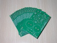
New bug free pcb available!
New version PCB is fab out!
Modifications:
1. connected collectors of Q8 and Q3 (which was missing on the first version)
2. modified footprint of potentiometers. Multi turn pots can also be mounted
3. fixed the bug of small hole for Q8.
4. added a 220uf cap on feedback path. In this case the VR1 should be changed to 2k. The capacitor is an optional component. If you don't need it just short 2 pins of the cap and change VR1 to 200Ohm.
5. footprint of Q1 and Q2 are modified to which TO-3PL transistors like 2SC3280 can be assembly on board directly.
Free boards keep on offering:
FREE JLH Class A Amplifier PCB
Attachments
Zeon,
click on the link in post 21.
That's where you order.
A post on the thread does nothing, expect tell everyone you won't or can't read.
click on the link in post 21.
That's where you order.
A post on the thread does nothing, expect tell everyone you won't or can't read.
Have just placed my order for 2 pieces with MJ15003 semis.
Would be interested if there's someone making PCBs for the original 68 (69?) design too.
Would like to compare the two (already have components for the single supply design -using MJ15003's as well).
Also like to try Hiraga Class A ....
Would be interested if there's someone making PCBs for the original 68 (69?) design too.
Would like to compare the two (already have components for the single supply design -using MJ15003's as well).
Also like to try Hiraga Class A ....
Feedback
I begin to receive feedbacks. The first comes from Jeff of UK. He reported there's noticable 50Hz noise in his amplifier. I believe this is due to the power supply because I can't heard any noise with my regulated power supply board. After a few emails I know that Jeff's power supply has only 6800uf filter capacitor. He just connect a dual 15V power transformer to the board through a bridge rectifier. This is far from enough for a Class-A amplifier, which is very sensitivity to the power supply noise. I sueegested him to connect more capacitor to the power supply, and he did. The result is quite positive. When connected 10000uf the noise is reduced sigificant. When increase to 47000uf, there's no noticable noise can be heard from the speaker.
Conclusion: JLH power amp is very sensitive to power supply ripples. Very large capacitors are necessary. I strongly suggest a regulated power supply for it since I got very good result with it. The noise is even lower than a non regulated power supply with 68000uf capacitor.
A customer in Australia, Alan, discussed with me about the power supply for JLH amplifier. He send me the circuit of his power supply board, I tried it today and get good result. The circuit is quite simple, just a Darlington capacitor multipler:
This is my testing board
Don't have 2N2955 so replaced with 2SA1215. The 1k resisotor is replaced with 510Ohm to reduce the voltage dropout. The overall current is 3.2A, a small heatsink can keep the transistors from overheating.
The purpose of this circuit is to reduce the 50/60Hz noise. It doesn't really performance like a huge capacitor that can provide power for large dynamic audio signals. A pair of large cap is still necessary for the JLH amp.
An externally hosted image should be here but it was not working when we last tested it.
This is my testing board
An externally hosted image should be here but it was not working when we last tested it.
Don't have 2N2955 so replaced with 2SA1215. The 1k resisotor is replaced with 510Ohm to reduce the voltage dropout. The overall current is 3.2A, a small heatsink can keep the transistors from overheating.
The purpose of this circuit is to reduce the 50/60Hz noise. It doesn't really performance like a huge capacitor that can provide power for large dynamic audio signals. A pair of large cap is still necessary for the JLH amp.
The schematic you have posted does not show a capacitance multiplier.
It needs a resistor for that.
JLH designed the ripple eater.
I suspect the JLH ripple eater would be compatible with the JLH amplifier.
It needs a resistor for that.
JLH designed the ripple eater.
I suspect the JLH ripple eater would be compatible with the JLH amplifier.
In my opinion R5 and R6 in JLH's design is not necessary for the cap multiplier. It will increase the output voltage dropout. Alan's design works great for my JLH amp. No hum can be heard even with ears 10cms away from the speakere
New version PCB is fab out!
Modifications:
1. connected collectors of Q8 and Q3 (which was missing on the first version)
2. modified footprint of potentiometers. Multi turn pots can also be mounted
3. fixed the bug of small hole for Q8.
4. added a 220uf cap on feedback path. In this case the VR1 should be changed to 2k. The capacitor is an optional component. If you don't need it just short 2 pins of the cap and change VR1 to 200Ohm.
5. footprint of Q1 and Q2 are modified to which TO-3PL transistors like 2SC3280 can be assembly on board directly.
Free boards keep on offering:
FREE JLH Class A Amplifier PCB
Hi, Siliconray,
Please clarify which schematic shown in the Class A Amp Site (is it fig 2, the final circuit?) that your kit is based on?
Thanks!
Lo_tse
yes the fig 2. there's a capacitor in the feedback path, I suggest short the 2 pins of the cap so that to have a DC loop and 200 Ohm potentialmeter can be used as VR1
yes the fig 2. there's a capacitor in the feedback path, I suggest short the 2 pins of the cap so that to have a DC loop and 200 Ohm potentialmeter can be used as VR1
Got it. Thank you for the prompt repsonse.
Lo_tse
G'day,
Got my boards finished today, very stable using MJL4281, have a small cap across the feedback. Everything else per the drawing with BC560C everywhere, running with 24V rails, iq 1.7A.
Had a quick listen sounds great so far, on soak now for a few hours then give it a good listen.
Regards
Bruce 😎
Got my boards finished today, very stable using MJL4281, have a small cap across the feedback. Everything else per the drawing with BC560C everywhere, running with 24V rails, iq 1.7A.
Had a quick listen sounds great so far, on soak now for a few hours then give it a good listen.
Regards
Bruce 😎
Max supply rails for this design?
Hi all,
Anybody try higher supply rail voltages (and what were they) with success on this design?
Just interested how far the design can be pushed IRO power output.
Hi all,
Anybody try higher supply rail voltages (and what were they) with success on this design?
Just interested how far the design can be pushed IRO power output.
G'day,
Got my boards finished today, very stable using MJL4281, have a small cap across the feedback. Everything else per the drawing with BC560C everywhere, running with 24V rails, iq 1.7A.
Had a quick listen sounds great so far, on soak now for a few hours then give it a good listen.
Regards
Bruce 😎
Hi Bruce
Any further thoughts on the sound after running in the caps ?
I am getting the parts to build soon .
regards
kp93300
I have just ordered a couple of these boards to try, should be interesting to compare to the original designs and the HART design that I sell.
Has any body already finished the assembly? I'm looking forward to see your testing results and reviews..
- Home
- More Vendors...
- Siliconray Online Electronics Store
- ★★ Free PCB for JLH 2005 Class-A Amplifier