maybe we ask:
are you towing a caravan, or transporting a blonde?
Would a blonde know the difference? Maybe the blonde and caravan is a better combination.🙂
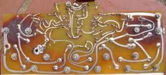
Bedini amp and psu circuit
Here they are gents. Very roughly drawn on paper; I don't have software to do this neatly unfortunately. Notice the lack of regulation in the psu - very basic. When I rebuild the Bedini will add in regulator module to see (hear) the difference. This is going to take some time to get to but hopefully not more than a year. BTW I've had this amp for more than 25 years and only switched it off when we moved (3 times) and when minor repairs had to be done - replaced reservoir caps and feed-forward caps (47uF went soft to 25uF and gain climbed considerably in that channel; did both channels). The rebuild is going to be done into a new chassis (bigger) with separate transformer per channel and better heatsinking.
Regards,
Kevin
Attachments
Here they are gents. Very roughly drawn on paper;
Kevin
Thank you Kevin, nice job. When you visit we can talk about how to rebuild your amp.
I built a JLH only late last year purely to experience the charismatic sound that many enthusiasts claimed, but I did not become a converted. It does sound very nice but not for too long. (In my opinion) Most likely it does not partners well with my very inefficient speakers.
I learn't my electronics by pouring over this cct for a long time and eventually I think I got the hang of what was going on 🙂
I also was not overly impressed with the sound and some of the mods I subsequently did that I thought improved things I think are regarded as a heresy by some true believers - I guess we are not all looking for the same things from our audio systems - and I think it would have to be quite a large implementation to deal well with inefficient speaker.
Member
Joined 2009
Paid Member
I am building one again 🙂 The chassis i am making weights 15Kg already without anything inside of it 🙂 I expect total weight of about 25Kg. Found a very nice 2SC2922 output transistors. It needs about 10pcs to match them for a stereo amplifier. Not that many at all. The expected Power dissipation should be around 130W per chassis.
Just have no idea how much capacitance ill be needing with 30V power supply voltage. So far I ordered 90.000uF total. But i think it will be too little.
wow, that's what I call an amplifier ! 😎
I'd try the caps you've ordered. If it's not enough, maybe a choke could be helpful.
choking up
+1 But finding (vs ordering custom) iron can be hard. I've had some success with misusing the secondary of EI power transformers.
To date I've been too lazy to rewind anything but that should also be a possibility
it's not enough, maybe a choke could be helpful.
+1 But finding (vs ordering custom) iron can be hard. I've had some success with misusing the secondary of EI power transformers.
To date I've been too lazy to rewind anything but that should also be a possibility
I routinely "misuse" the secondaries of EI transformers as chokes - some purist don't seem to like the idea because of the partial loss of inductance caused by core saturation but allowances can be made for that and what that leaves is a quick & easy, fairly cheap supply of chokes with different R / L combinations readily available ( for now ).
Hmm, interesting idea with the secondary as a choke. Have never tried that. What is the worst case scenario doing that? 🙂 I kinda think its cheapier to buy achooke instead of using a normal transformer.
PS
Cant find any suitable choke on the internet (only for tube amps). Has anyone a link maybe?
PS
Cant find any suitable choke on the internet (only for tube amps). Has anyone a link maybe?
I only use these for low Voltage / high current solid state class A type amps.
These only need very small choke values for extremely effective filtration ( 1 - 5mH ) so it is really easy to use any kind of a winding found in commercial EI trannies.
Valve amp designs need much bigger inductor values because of the high voltage / low current environment and this makes the design of the choke much more of a specialist "black art" kind of a thing, necessary to tailor the frequency & quality of resonance.
In the much smaller choke values that solid state amps need these problems don't really arise.
I suspect for valve amps you will need to buy purpose built chokes - sorry about that but laws of nature are not optional 😉
Ok then, i was looking for much bigger inductance 🙂
Those ill find at home in a drawerand will give it a try. I was planning to use a resistor but choke is a nice option too then.
Those ill find at home in a drawerand will give it a try. I was planning to use a resistor but choke is a nice option too then.
An externally hosted image should be here but it was not working when we last tested it.
The choke you show is a macro shot of a rather small common mode choke - probably height about 50mm total.
If I was building valve amps I would try a resistor in series with a small choke 🙂
If I was building valve amps I would try a resistor in series with a small choke 🙂
And with a ferrite torroid core - not a good choice if you're running DCThe choke you show is a macro shot of a rather small common mode choke - probably height about 50mm total.
Probably one of the most approachable articles is Input Choke & Resonant Choke Power Supplies for RF Linear Amplifiers (by Tony IØJX & Pesa IKØHIT)
If you do the math you'll find you don't need much inductance for deep Class A sand amps as long as the core is big enough not to be completely saturated: a 12VAC or there abouts secondary EI transformer of about the same size as your mains transformer will likely be in the right ball park.
Try it and measure the results.
Last edited:
Try it and measure the results.
There's also a thread on estimating transformer magnetic behaviour here
And with a ferrite torroid core - not a good choice if you're running DC
Well, it's just fine with DC if you run it in common mode as it's designed for - because the opposing currents cancel the flux - but I guess that may not be what you need.
Well, it's just fine with DC if you run it in common mode as it's designed for - because the opposing currents cancel the flux - but I guess that may not be what you need.
Not in this case
Even a full wave rectifier/split rail solution would end up with DC in the core. I think?!
What case ? I thought he wanted a choke for a tube amp but I have not seen the schematic so I cannot comment about any case . . . .
Just saying if you using this common mode choke as intended the DC currents cancel and that's why the core can be so tiny for such large currents.
As it was not intended for a tube design it might not be very relevant to the "case" whatever it might be
Just saying if you using this common mode choke as intended the DC currents cancel and that's why the core can be so tiny for such large currents.
As it was not intended for a tube design it might not be very relevant to the "case" whatever it might be
What case ?
Sorry - I thought we were talking about a JLH amplifier. Ergo single rail, 2 amps (per channel) at 36+volts I clearly missed something somewhere
Yes, and a choke instead of a resistor in a power supply with a capacitor-resistor (or choke)-capacitor.
I'm afraid that you read a little bit more on how to build this thing and how to fire it up, else you'll probably fire it up.
In short, be sure to have low rail voltage (eg 5V or so) and have one of these variable resistors adjusted so that you have minimum bias current. Then adjust DC offset, let it warm up a little more and keep DC offset small.
The start increasing bias current. If everything is still ok, go for higher rails voltage and gradually work your way up to the desired Ig (bias current) while keeping DC-offset close to 0.
succes, MArco
P.S. don't forget to read more ...
I posted this in March with the intention of getting the amp up and running. I am only just about to finish it. With regard to VR1, VR2 and VR3 what is the order for checking bias and dc offset, i.e in which order do I adjust them?
Thanks. Rob.
- Home
- Amplifiers
- Solid State
- JLH 10 Watt class A amplifier