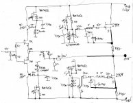
No diodes? How about CCS? Otherwise it seems that the bias voltage would change with power-line fluctuations.
according to myexperience with SJEP's , for decent thermal all you need is few LED/diodes in bias circ , and usual (+25-30C) heatsink
I can bet that Pa is not using diodes at all
but , I'm mu about value of Rs in origigi F6 , there must be few things left , which old Fox count on , and we aren't even aware of
What is the use of Rs if outside the bias circuit? (appart from measurement)
i do not understand.
i do not understand.
Isn't using both LEDs and CCSes like wearing a belt and suspenders? 
I do not understand "bootstrapped resistor divider" in this application. In the idle state, there isn't any bootstrapping possible. What determines the reference voltage or current?
QUOTE=Zen Mod;3159277]bootstrapped resistor divider is completely fine
but , I like to use CCS-es , same as plenty of green LED's
 [/QUOTE]

I do not understand "bootstrapped resistor divider" in this application. In the idle state, there isn't any bootstrapping possible. What determines the reference voltage or current?
QUOTE=Zen Mod;3159277]bootstrapped resistor divider is completely fine
but , I like to use CCS-es , same as plenty of green LED's
 [/QUOTE]
lhquam: A key question still hangs: What is the sonic print of Teaser-6 driving your B&W loudspeakers? Your last report at a Zo = 1800 milliOhms said it gave a boomy bass, with a muddy midrange and was fatiguing. The time is here to answer it with ClG = 2 -3. at an average Zo ~ 150 milliOhms. I would also go with CLG = 1 using the same input signal level of the original design point of CLG which gave Teaser-6 full power. This sonic print at this best case scenario of lowest Zo is impractical; but you may still need to know the best performance Teaser-6 gives anyway. It is a transient experiment, and you'll have subjective and objective data as a function of CLG.A CLG of 1 would be a bit extreme - the input JFETs would have to run at full rail voltages. CLG= 2 or 3 should be ok.
CLG=3 (actually 2.9) gives Zo=0R195 DF=41.
CLG=2 (actually 1.96) gives Zo=0R132, DF=60.6
Rs is outside modulation circ, but inside bias circ
What's Rs job then.
There are some limits on mods to the PCB without major surgery. The mods to (optionally) remove degeneration by the source resistors are trivial. Getting CLG down to near 1 is more difficult because of the V2 supplies. Also, my signal source is an M-Audio AP-192 board with peak output of about 2.7V. That implies that the THD tests would be at below 0.5 watt max.
My next step is to remove the source degeneration, make some measurements and listen for a while.
My next step is to remove the source degeneration, make some measurements and listen for a while.
lhquam: A key question still hangs: What is the sonic print of Teaser-6 driving your B&W loudspeakers? Your last report at a Zo = 1800 milliOhms said it gave a boomy bass, with a muddy midrange and was fatiguing. The time is here to answer it with ClG = 2 -3. at an average Zo ~ 150 milliOhms. I would also go with CLG = 1 using the same input signal level of the original design point of CLG which gave Teaser-6 full power. This sonic print at this best case scenario of lowest Zo is impractical; but you may still need to know the best performance Teaser-6 gives anyway. It is a transient experiment, and you'll have subjective and objective data as a function of CLG.
Measurement of bias current and bias stability. Rs can probably be much less than 0R47 for both purposes.
What's Rs job then.
[/QUOTE]Isn't using both LEDs and CCSes like wearing a belt and suspenders?
I do not understand "bootstrapped resistor divider" in this application. In the idle state, there isn't any bootstrapping possible. What determines the reference voltage or current?
QUOTE=Zen Mod;3159277]bootstrapped resistor divider is completely fine
but , I like to use CCS-es , same as plenty of green LED's

what's wrong with double naked ?

as I said, I like it that way
bootstrapped,bypassed,whatever ...... one moment is one , other moment is another one
see all small amps ,recently shown by Papa ; bias solution is always simplest possible
he's most genuine Fearless Amp Builder 😀
Measurement of bias current and bias stability. .
but in different order 😉
Rs can probably be much less than 0R47 for both purposes.
certainly . but only in case of having decent measuring equipment , one can choose fave value - lower or higher than 0R47
moi thinks that THD spectra is thing to observe
what's wrong with double naked ?
as I said, I like it that way
I like it that way too
Just go naked
It sounds better
what's wrong with double naked ?
What are the belt and suspenders holding up then?
Double naked focus one on the listening as all other alternatives are unacceptable😀 Melon has perfect pic for occasion but it has drawn too much attention, taking interest away from amps

- Home
- Amplifiers
- Pass Labs
- F6 Amplifier

