IDSS & Oscillation
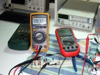
Guys when you are going to measure those for IDSS take caution. In case they will be genuine their high Yfs and capacitance can set them off and trick out the measurement setup. I have a few in my stash from years ago which have the right looks, bought in Japan. Have used them before in circuits. I was fiddling with them again to sort out a quad for the new experiment we are up to. Rat hint was when I saw 10-20% play between DMMs in series mA mode for same sample. I decided to investigate. First I looked if it was about burden voltage due to differences in the internal shunt resistor of the DMMs when in mA mode. One has 2.5R other has 5R and another 10R. So I thought it may be influential with those JFETs initially. But it was not that. I set up a 3.3K dummy at 10V PSU and put them in series. All three DMMs were spot on 3mA and very close between them in the last digits. Then I used a 10 Ohm in series with the JFET, set the DMMs in mV parallel mode to see what happens when using the voltage drop method that gets them out of the way. Worse! up to -20/+40% incompatible readings. But I spotted something. The worse the deviation, the more the PSU was indicating a few hundred mV change on its original 10V setting. That's it, oscillation due to all this cabling and DMM internals. Only one DMM would not bother in series mode, but it would bother the most in parallel mode. Parallel Rdrop method indicating in mV was the jumpier anyway. So take caution, make the breadboarding tight and have a DMM in voltage mode parallel to the PSU or battery. Watch that the power source does not jump its voltage reading in the hundreds of mV when you close circuit measuring IDSS. It did go tricky with battery too by the way. Now it may be my cables and set-up or not, but watch out for it creeping in because the parts are going to bias differently in circuit then and they may shut down the input stage for amplifying even, since the current is allocated after a resistor CCS to a certain share between branches. Those parts are not useful for many other uses and are quirky so don't invest in any number than a few, especially in the face of getting the fakes risk. If genuine they bunch well so not many drop outs anyway. What you see in the pic is a 10mA one when all things calm but misbehaving at that shot setting. I tried on K170BL all the above methods, no problems. So the 369s are quirkier is the difference.
Found some 2SK369 on ebay. Do you think they are fakes?
I got same 2SK369 on their way hopefully they be the real thing and build as on post 7881
Guys when you are going to measure those for IDSS take caution. In case they will be genuine their high Yfs and capacitance can set them off and trick out the measurement setup. I have a few in my stash from years ago which have the right looks, bought in Japan. Have used them before in circuits. I was fiddling with them again to sort out a quad for the new experiment we are up to. Rat hint was when I saw 10-20% play between DMMs in series mA mode for same sample. I decided to investigate. First I looked if it was about burden voltage due to differences in the internal shunt resistor of the DMMs when in mA mode. One has 2.5R other has 5R and another 10R. So I thought it may be influential with those JFETs initially. But it was not that. I set up a 3.3K dummy at 10V PSU and put them in series. All three DMMs were spot on 3mA and very close between them in the last digits. Then I used a 10 Ohm in series with the JFET, set the DMMs in mV parallel mode to see what happens when using the voltage drop method that gets them out of the way. Worse! up to -20/+40% incompatible readings. But I spotted something. The worse the deviation, the more the PSU was indicating a few hundred mV change on its original 10V setting. That's it, oscillation due to all this cabling and DMM internals. Only one DMM would not bother in series mode, but it would bother the most in parallel mode. Parallel Rdrop method indicating in mV was the jumpier anyway. So take caution, make the breadboarding tight and have a DMM in voltage mode parallel to the PSU or battery. Watch that the power source does not jump its voltage reading in the hundreds of mV when you close circuit measuring IDSS. It did go tricky with battery too by the way. Now it may be my cables and set-up or not, but watch out for it creeping in because the parts are going to bias differently in circuit then and they may shut down the input stage for amplifying even, since the current is allocated after a resistor CCS to a certain share between branches. Those parts are not useful for many other uses and are quirky so don't invest in any number than a few, especially in the face of getting the fakes risk. If genuine they bunch well so not many drop outs anyway. What you see in the pic is a 10mA one when all things calm but misbehaving at that shot setting. I tried on K170BL all the above methods, no problems. So the 369s are quirkier is the difference.
Attachments
Will have to come again to the island and evaluate in your horn speakers the phono twists at a point in fall in case they will be promising. You won Lynn Olson's blessings I saw. Nice.
You are welcome anytime!
Your help with my speakers was invaluable.
Don' t forget the new TSSA amp is on the line too!
Your help with my speakers was invaluable.
Don' t forget the new TSSA amp is on the line too!
Ok, here it is for classic 4XK170BL. You may relax the matching for the quads since they are degenerated enough to share current at ~0.75*IDSS and the total transconductance (~130mS) will be steady for 7.5-9mA samples at shared ID. But make sure that the sum total of the quads IDSS between channels is nearly the same. So the folded cascodes will be sparing the same drive current to R16 and same gain. No loop feedback here to match the gain if not thorough with JFETs picking in both stages. It should present ~15 Ohm input equivalent noise resistance, not bad. And some better input headroom, adequate for normal MC also. Pick a ~5mA BF245A for Q8 and circa 15mA BF245C for Q5.
Hi Salas
Can we use J310 instead of BF245C for Q5 ?
What are the main differences between them ?
J310 around 40mA Fairchild gives me twice as much Vgs (=Vds across 8mA K170 under it in full IDSS cascode CCS test) compared to 15mA BF245C Fairchild. So take care not to see more than 7.9V across your K170 when you will apply with your Rs. After that point gate leakage jumps. There are linearity and noise differences between 245 & 310 which do not impose them selves in this config enough.
Thanks for the advise Salas!
P.S. A tiny lead jumper between G & S next to them instead of breadboard pin wire keeps 369s less trigger happy during Idss sorting.
That's short path, its good for less inductance between gs, only it delays you exchanging them and there is a risk for accidental shorts in series mode blowing some mA range DMM fuse.
I already ordered a breadboard I didn' t have for testing.
Measured lots of fets so far no fuse blown on DMM. But I' ll keep that in mind.
Of course it' s not the faster method.
Measured lots of fets so far no fuse blown on DMM. But I' ll keep that in mind.
Of course it' s not the faster method.
Measured lots of fets so far no fuse blown on DMM.
I blew a $30 DMM fuse doing this. I now measure voltage.
Rush
A 1k0 series resistor connected to +ve supply.
Clip the G+S together and connect to -ve supply.
Attach DVM across the 1k0.
now tap a wire from 1k0 to D of DUT.
In worst case short a 20Vdc supply will pass 20mA, That's 400mW through the resistor.
In the no short condition the DVM reading in Vdc is equivalent to the mA of current passing.
if the Vds is equal to the manufacturers specified test voltage and if the Tj is equal to the manufacturers specified test temperature then that mA reading is the Idss.
The best we can achieve is a close approximation to Idss, due to errors in Tj. We can get very close on Vds, but super accuracy here is wasted if Tj is wrong.
Salas,
7.9Vds is perfectly within range of a 2sk170 Lsk170 for avoiding excessive gate leakage current.
Most designers/builders who make comment on this gate leakage issue are referring to Vds >>10Vds and Id>=Idss.
7.9Vds is ~half the voltage that might cause a problem, if Id were high and Tj was high.
7.9Vds is perfectly within range of a 2sk170 Lsk170 for avoiding excessive gate leakage current.
Most designers/builders who make comment on this gate leakage issue are referring to Vds >>10Vds and Id>=Idss.
7.9Vds is ~half the voltage that might cause a problem, if Id were high and Tj was high.
I believe 7.9V is the minimum Vd to use with K170 to avoid non linearities.
In the Simplistic first stage, Salas bias the cascode bjt at around 8v so we get 7.9V for Vd in the lower k170.
In the Simplistic first stage, Salas bias the cascode bjt at around 8v so we get 7.9V for Vd in the lower k170.
J310 around 40mA Fairchild gives me twice as much Vgs (=Vds across 8mA K170 under it in full IDSS cascode CCS test) compared to 15mA BF245C Fairchild. So take care not to see more than 7.9V across your K170 when you will apply with your Rs. After that point gate leakage jumps. There are linearity and noise differences between 245 & 310 which do not impose them selves in this config enough.
So BF245C is a much better choice.
Fortunately BF245C is easily obtainable here throu Distrelec.... I am now working in the layout to mod my 48db build 🙂
Hi Salas... do you knw these EMZ caps: https://www.distrelec.ch/ishop/Datasheets/jiEMZ-B33063B_de.pdf ?
After cascoding the second stage I will need to retrim the high freq cap... can I use those EMZ ?
After cascoding the second stage I will need to retrim the high freq cap... can I use those EMZ ?
So BF245C is a much better choice.
Fortunately BF245C is easily obtainable here throu Distrelec.... I am now working in the layout to mod my 48db build 🙂
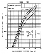
No its not much better per se in cascode. Its just tamer for Vgs. In the cascode the upper Jfet's noise won't directly correlate with the lower Jfet's that sets that performance. 245 15mA and 170 8mA did a clean swing of 12Vpp in a test I run with less B+,Rs, and RL than the projected 2nd stage values. It will likely be a bit more in the phono. So its enough. You can use J310 anytime too, logically. Although I did not run that exactly in the same way yet. I did in cascode CCS full Idss mode. There I saw its happier for Vgs naturally due to its high Idss characteristic of course. There is a Toshiba chart showing the Igsx VS Vds & Id leakage thing for K170. Interpretation depends on what is considered high regarding the input signal level and how high is Rg (few mV & 1Meg in our case). All Id levels follow the trend non the less (our 2nd stage is at about 4mA Id). Should be more at higher than 25C also.
Attachments
Hi Salas... do you knw these EMZ caps: https://www.distrelec.ch/ishop/Datasheets/jiEMZ-B33063B_de.pdf ?
After cascoding the second stage I will need to retrim the high freq cap... can I use those EMZ ?
Haven't used any that I remember of, only a friend had an MZ crap bike when we were 15 and had some silly falls, but EMZ look far more decent in what they do.😀
Haven't used any that I remember of, only a friend had an MZ crap bike when we were 15 and had some silly falls, but EMZ look far more decent in what they do.😀
Anyway.. the word crap is there so.... what do you think about wima FKP ?
- Home
- Source & Line
- Analogue Source
- Simplistic NJFET RIAA