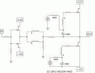
I think this won't give you the perfection of symmetry that others here
seem to be striving for - the bias source will subtly modulate the signal.
😎
And maybe that's not a bad thing.
Rogers A100/Vox supreme e. g. - go to post #54/55 and post #79 aboutMr. Pass. You called Conceptual F6 a Classic. Todate, no one has asked you: what is the precedent schematic of this classic old design you used to resurect it as Conceptual F6? Please show us a specific schematic of this old classic. It will be valuable to DIYers to compare with their ongoing designs to revive it.
http://www.diyaudio.com/forums/soli...odels-quasi-complementary-power-output-6.html
Last edited:
And maybe that's not a bad thing.
What "I" think he is saying is that, the bias refrenced to gnd will not float the top FET with the Vout node and the bottom FET drain. Not only will the top FET not be a CS anymore but the only variability then would be the few volts of transformer signal.
As the simplified dwg shows, the output top FET bias is tied and floats above, the Vout node.


Rogers A100/Vox supreme e. g. - go to post #54/55 and post #79 about
http://www.diyaudio.com/forums/soli...odels-quasi-complementary-power-output-6.html
The specific schematics in the previous post, and others presented in past ones have a general structure [or topology] like that of Conceptual F6. I believe that any one of them fits the description of the basis classic design. IMHO, Mr. Pass infused this old parent design with current new-technology semiconductors and passives [absent in the 1960s], plus his extensive and exclusive know-how to create his Conceptual F6.
DIYers have focused their attention on Conceptual F6, and may have ignored the [great] value embodied in the old parent classic. The parent designs from the 1960s contain all of the principal principles of operation which are needed to implement a working Conceptual F6. For example, where does the bias to the upper JFET need to be referenced to in Conceptual F6? Clearly the best solution is to the output port as shown in the old trusted design.
How close is the design of your Conceptual F6 to that of the parent classic?
The first time I saw a design like the F6 came from this Delco application note:
http://www.updatemydynaco.com/HistoricDocuments/Delco100Watt.pdf
I remember at the time I didn't have a clue how to make a +/- 50V power supply.
http://www.updatemydynaco.com/HistoricDocuments/Delco100Watt.pdf
I remember at the time I didn't have a clue how to make a +/- 50V power supply.
I bet I can blow it up. All this time I thought I liked electronics, when in fact i need to be in explosives. Just burnt up a SS R085,,,,by accident of course😀
I believe that Mr. Pass took a classic as in the above link, and ugraded it dramatically. For example; the very low distortion, high power, and simplicity etc. of Conceptual F6. I hope this analogy fits; it is like improving a 1956 Chevy to a Chevy Volt!The first time I saw a design like the F6 came from this Delco application note:
http://www.updatemydynaco.com/HistoricDocuments/Delco100Watt.pdf
I remember at the time I didn't have a clue how to make a +/- 50V power supply.
I bet I can blow it up. All this time I thought I liked electronics, when in fact i need to be in explosives. Just burnt up a SS R085,,,,by accident of course😀
It's a dpletion mode part. It's high current also. You have to be ready, with proper gate control before you turn it on 😀
And of coarse watch the Pd 😀
Thank you for that URL. Where are the button "Historic Documents" aboutThe first time I saw a design like the F6 came from this Delco application note:
http://www.updatemydynaco.com/HistoricDocuments/Delco100Watt.pdf
I remember at the time I didn't have a clue how to make a +/- 50V power supply.
Update My Dynaco
for getting the overview?
Thank you for that URL. Where are the button "Historic Documents" about
Update My Dynaco
for getting the overview?
I don't know how to find other documents. You might just try truncating the URL. I used a Google search that took me right to it. I think I originally saw the amp schematic in Popular Electronics without the power supply.
That's why I use current limited bench supplies for testing.😱It was raw current. Happened so fast it didn't even burn. Gotta love that kind of potential.

Circle walking is a very famous martial arts technique called bagua zhang....
as long as Papa is not disturbing us, we circle on.....😀

I took the time this morning to review my history of posts in this thread,
and I conclude that you would benefit from some additional information.
Notice the particular placement of capacitors, resistors, and transformer
secondaries which give greater output DC offset stability without
sacrificing the symmetry of the two halves at AC.
😎
and I conclude that you would benefit from some additional information.
Notice the particular placement of capacitors, resistors, and transformer
secondaries which give greater output DC offset stability without
sacrificing the symmetry of the two halves at AC.
😎
Attachments
Circle walking is a very famous martial arts technique called bagua zhang....
....
yup
but bagua zhang certainly doesn't include increasing level of confusion
NB that I certainly had my deal in same ........ (confusion , not bagua zhang
 )
)yup
but bagua zhang certainly doesn't include increasing level of confusion
Good answer, indeed it clarifies...!
NB that I certainly had my deal in same ........ (confusion , not bagua zhang)
Yes, but never a thread was so productive before Nelson published the circuit...
I have great respect in your "circling"
And Nelson showed mercy just now, very fine coincidence......
Now circling can start again in the other direction.....😀
- Home
- Amplifiers
- Pass Labs
- F6 Amplifier

