You got it right. Just use a file but be careful not to go too far as that will let the leads flop around in the sockets.. Sneak up gradually on a clean but snug fit. Use a very fine file that doesn't remove too much material on a single stroke.
Last edited:
I should add that the sockets can take only so much manipulation when installed on the board. A preferred method is to use a spare socket off board and fit it over the lead as you adjust the size.
I had better luck using needle nose pliers (on each lead close to the end) rather than fingers for the final insertion on the build. I don't even try to do a swap or rotation without those, good lighting and some sort of magnification.
I had better luck using needle nose pliers (on each lead close to the end) rather than fingers for the final insertion on the build. I don't even try to do a swap or rotation without those, good lighting and some sort of magnification.
Last edited:
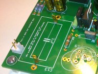
For you guys that have used these sockets before, what do you do when the leads are too thick? My thought was to file down a short section of lead to fit. Open for ideas. I am hoping to socket and compare C9 and C13
Hi Jac,
as Bob already pointed out using a file you can do it.
But for bigger leads (like C13 ones) PCB mount faston tabs (Mouser 571-63756-1) are a better choice than sockets:
Attachments
Last edited:
I powered up both channels and something is wrong and i cant understand what. Voltage across 3886 and 318 are ok but relay does not click. I dont have CC on output but the voltage acros relay coil is 12 volt. Infact before R14 ihave 24v but after i have almost 12v the same like on relay coil.
R14 is a bit warm.
R14 is a bit warm.
Yes the error is the sameon both channels. The leds are ON but normally a should have 24v across D4 (diode paraleled with relay coil) but i have only 12v.
I will try to disconect R14 and see if without protection circuit connected i can measure 24v.
LE. Seems that DC protection is hungry. Disconnected R14 and i have 23v before and after. I will take a closer look to the DC protection circuit.
I will try to disconect R14 and see if without protection circuit connected i can measure 24v.
LE. Seems that DC protection is hungry. Disconnected R14 and i have 23v before and after. I will take a closer look to the DC protection circuit.
Last edited:
The relay needs about 15 volts to activate. Reduce the 470 Ohm resistor to 220 Ohms and try it again.
O.T. Got a reply from Uriah and he is feeling much better and is making good progress in his situation. Let's keep him in our thoughts and prayers.
Found the problem! Someone from Mouser put 0.82k resistors instead of 220k resistors.
Now my relays clicks !
OT Good for Uriah !
Now my relays clicks !
OT Good for Uriah !
O.T. Got a reply from Uriah and he is feeling much better and is making good progress in his situation. Let's keep him in our thoughts and prayers.
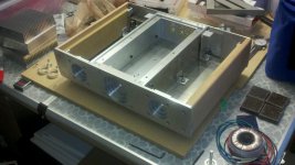
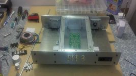
Great to hear! And speaking of Uriah, here are a couple pics of the lighter note that I am building to go with the FE.
Attachments
O.T. Got a reply from Uriah and he is feeling much better and is making good progress in his situation. Let's keep him in our thoughts and prayers.
nice to read... 🙂
My Myref FE RC is singing from few hours already. First thing noticed is that the all 4 LM317's are running hot and i think a smal heatsink would be good.
Also my LM3886 are running a bit hot but this is because my heatsink from Banzai Music is not flat enough and the contact surface is not perfect flat. I was thinking to put some aluminium foil between IC and heatsink because the thermal paste is not enough.
About sound quality after burn in and after i buy the next speakers as my previuous i sold for upgrade. Now i'm using some poor Sont speakers for tests.
Last edited:
Congratulations! And then there were 6 😀
Have you reached temps that trigger the self-protection on the LM3886?
Have you reached temps that trigger the self-protection on the LM3886?
NO but i can "feel" with my bare finger that the chip is hot and the heatsink is cold.
Last edited:
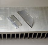
Don't know if you want to go through the hassle, but there is a fairly simple way to flatten the heat sink. You need a flat surface that can be anything from a piece of granite, marble, ceramic tile or even thick glassiness. A few sheets of wet-dry sandpaper attached with thin double sided carpet or carpenters tape. The grits should range from ~ 120 - 1600.
Draw a bunch of squiggly lines on the heat sink and do a few passes on the dry sandpaper to identify the high spots. If the surface is really bad, lay a file on the bench/table and draw the part across it to get close. Then add water and work up through the grits. You should be able to get to a point where scraping the surface with the blade of a utility knife produces a full width impression. You now have a flat surface. If your heat sink is very large just using the blade as a scraper on the LM3886 contact area can be very effective.
It is not a one time system as the same setup can be used to create a great brushed satin finish chassis parts. In that case you draw the part across the sandpaper in only one direction.
Attachments
Last edited:
- Status
- Not open for further replies.
- Home
- Amplifiers
- Chip Amps
- My_Ref Fremen Edition RC - Build thread