it woun't have clarity as tl074/84 🙂
your saying about clarity...its way beyond dude....i get a huge short accros the series....when i connect fets dont know why...can u plz help me out
everything is ok the waveform on high is small in size than the low side.....comparable 3 times small i guess
Nonsense, it wouldnt work at all.it woun't have clarity as tl074/84 🙂
Look at the slew rates:
lm324: 0.4V/us
tl074: 15V/us
Lm wouldnt oscilate.
sweetperfume
If you are using lm's? Thats probably the reason your fets are smoking. 😉
Nonsense, it wouldnt work at all.
Look at the slew rates:
lm324: 0.4V/us
tl074: 15V/us
Lm wouldnt oscilate.
sweetperfume
If you are using lm's? Thats probably the reason your fets are smoking. 😉
gr8 thanks buddy.....but are u definite with ur opinion....and what would be the other reason if this aint be the prob
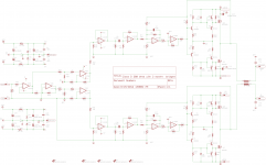
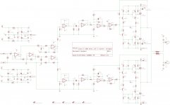
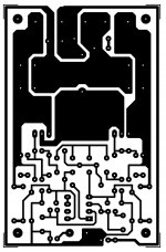
hi guys. the hi power version in bridge mode. i will upload artwork later 😉 😉
Attachments
Last edited:
Stewin, you sure love what you do! Great work!hi guys. the hi power version in bridge mode. i will upload artwork later 😉 😉
Stewin, you sure love what you do! Great work!
i thank GOD for his help . long time welcome back.
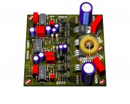
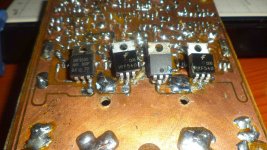
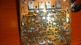
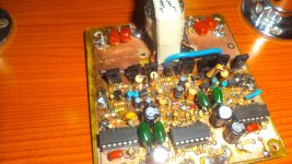
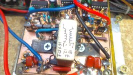
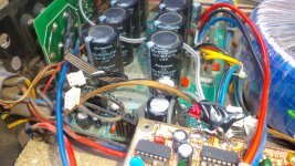
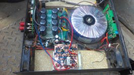
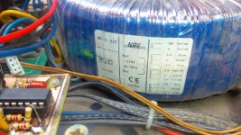
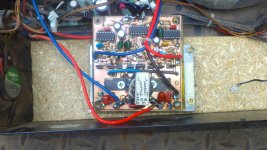
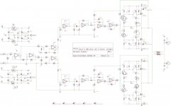
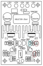
hi all i made bridged version and tested it but . when i pushed it hard with a 6ohm load that is a 18inch woofer the amp failed after 2 minitues. .i think my tracks for pcb were small the ones feeding the output fets. also
>>> btw the circled components were heating above normal.
here are the photos
>>> btw the circled components were heating above normal.
here are the photos
Attachments
-
 DSC03118_1.jpg472.8 KB · Views: 346
 -
 DSC03125_1.jpg499.3 KB · Views: 332
 -
 DSC03105_1.jpg408.4 KB · Views: 353
 -
 DSC03102_1.jpg408.1 KB · Views: 359
 -
 DSC03091_1.jpg414.6 KB · Views: 301
 -
 DSC03090_1.jpg499.8 KB · Views: 348
 -
 DSC03089_1.jpg528.9 KB · Views: 377
 -
 DSC03086_1.jpg453.4 KB · Views: 941
 -
 DSC03084_1.jpg417.9 KB · Views: 1,151
 -
 Class D 200 Wrms with 2 mosfet bridged schematic heating components_1_1.jpg154.3 KB · Views: 571
Last edited:
Use resistive load for testing...don't you care about your speakers and your ears?😀.
Also any amplifier must survive continuous rms power into resistive load to be reliable with music😎.
Also any amplifier must survive continuous rms power into resistive load to be reliable with music😎.
Use resistive load for testing...don't you care about your speakers and your ears?😀.
Also any amplifier must survive continuous rms power into resistive load to be reliable with music😎.
resistive loads like ? resistors in parallel to match impedance desired?
sweetperfume:
No,the opposite is correct😀.
A speaker is a non resistive load, in fact it is a nonliniar inductive/capacitive/resistive system depending on its configuration(single or multiple in cabinet and with or without filters).
stewin:
Power resistors with their resistance smaller than rated impedance, example: for 4 ohm impedance use 3 or even better 2.5 ohm low inductance resistors or resistor network
You simply draw the schematgic, assuming multisim has models for the components used, which as far as i know it should.
ni multisim doesnt hav models for ir2110 or irs2092. i hav seen several class d schematics with these two componets but i dont knw which cad was used. can anyone cum to my rescue please.
The schematic post 246 showing bridged class D may experience problem. Both halves may oscillate at different frequencies and some intermodulation product may be heard.
Bridge class D amp should be done using the same modulator or synchronized modulator.
Bridge class D amp should be done using the same modulator or synchronized modulator.
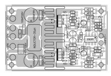
hi all just found this schema by detex audio . it seems simple . what makes it 100watts and not 200 watts?
😀 😀 😀
😀 😀 😀
Attachments


- Home
- Amplifiers
- Class D
- Ultra Simple Class D