2x Iron Powder Toroid Core T200-2, Iron Powder Toroid Core T157-6 items in urbasket eu store on eBay
this URBASKET EU STORE is a ripper please be careful in dealing with him ARTHUR
i hvae still not got my 10 t157-2 cores 3 MONTHS have passed
warm regards
andrew lebon
this URBASKET EU STORE is a ripper please be careful in dealing with him ARTHUR
i hvae still not got my 10 t157-2 cores 3 MONTHS have passed
warm regards
andrew lebon
original T106-2
An externally hosted image should be here but it was not working when we last tested it.
An externally hosted image should be here but it was not working when we last tested it.
An externally hosted image should be here but it was not working when we last tested it.
An externally hosted image should be here but it was not working when we last tested it.
An externally hosted image should be here but it was not working when we last tested it.
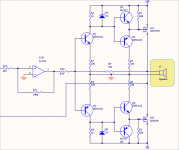
Connect Trasducer to this circuit
Hi!
Nice simple class D amp!
I was wondering if this amp would work fine in the 38-42 kHz range and what to do to connect it to a high impedance piezoelectric transducer (custom transformer I suppose). I want to start playing with relative high power ultrasounds 🙂
Thanks so much for any tip!
Hi!
Nice simple class D amp!
I was wondering if this amp would work fine in the 38-42 kHz range and what to do to connect it to a high impedance piezoelectric transducer (custom transformer I suppose). I want to start playing with relative high power ultrasounds 🙂
Thanks so much for any tip!
D
Deleted member 148505
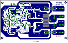
I've created a layout for this one.
I added trigger for protection circuit and added gate resistor diode.
Also adjusted some values for slightly higher than +-50V operation.
You can opt for the original values if you want it to run it for lower voltages.
I added the fuse so I can easily route the GND trace haha.
I added trigger for protection circuit and added gate resistor diode.
Also adjusted some values for slightly higher than +-50V operation.
You can opt for the original values if you want it to run it for lower voltages.
I added the fuse so I can easily route the GND trace haha.
Attachments
I've created a layout for this one.
I added trigger for protection circuit and added gate resistor diode.
Also adjusted some values for slightly higher than +-50V operation.
You can opt for the original values if you want it to run it for lower voltages.
I added the fuse so I can easily route the GND trace haha.
have you tested it with +/-56vlts successful , do the outputs or gate drivers heat or operate normal at that voltage ?
D
Deleted member 148505
D
Deleted member 148505
D
Deleted member 148505
I've created a layout for this one.
I added trigger for protection circuit and added gate resistor diode.
Also adjusted some values for slightly higher than +-50V operation.
You can opt for the original values if you want it to run it for lower voltages.
I added the fuse so I can easily route the GND trace haha.
you already have it armed?: D
Last edited:
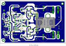
Here's my compact layout based on original schem by ejtagle.
redesign your work.🙂
D
Deleted member 148505
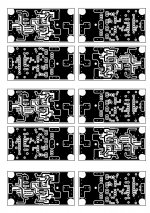
but after hearing the clarity of this amplifier i decided to use the original version which has been simulated by norazmi . here is my layout and artwork .
After reading through this entire thread I've decided to jump in and try to etch my own pcb. There are many different versions of this amp in this thread, but Stewin's layout and artwork look good. I do have a beginner question though. Most of the amps that people are building here are one sided but it looks like Stewin's pcb artwork is two-sided. Is that right?
Tom
Attachments
Thanks Norazmi, I was thinking maybe I should start out with a single sided board first. Is there a good, one-sided pcb of this ultra simple class D amp that you would recommend ? I have all the parts and would love to build it.
Tom
Tom
yes its ok for this design because its not so sensitive like ucd. your design seems good to go, but always double check for the component placement with right value. OCP is possible for this module and i`ll give it a try when i have time.
And yes i have one which im always made it because this amp is so cheap and hifi quality, give me your email and i`ll send it to you. you can go with your version and just match the value for the parts or else. 😀
And yes i have one which im always made it because this amp is so cheap and hifi quality, give me your email and i`ll send it to you. you can go with your version and just match the value for the parts or else. 😀
- Home
- Amplifiers
- Class D
- Ultra Simple Class D