I have a pair of 18 inch TC Sounds LMS Ultra 5400. Who has designs for them? Push-pull, bandpass etc.
Josh Ricci has designed a nice horn around those....
http://www.diyaudio.com/forums/subwoofers/189784-gjallerhorn.html
It's a huge heavy cabinet...
http://www.diyaudio.com/forums/subwoofers/189784-gjallerhorn.html
It's a huge heavy cabinet...
Last edited:
The pdf spec was -4dB @ 35Hz/ -10dB @ 28Hz.
The old website had it at 40-250Hz
My 2010 TH-118 pdf. reads:
40 Hz - 250 Hz -3dB
28 Hz - 300 Hz -10dB
The 2010 TH-115 pdf. reads:
38 Hz - 200 Hz -3dB
33 Hz - 280 Hz -10dB
Is the TH-112 new? Says it digs down to 33hz..interesting! I like 12" designs but don't see that many at all.
Is the TH-112 new? Says it digs down to 33hz..interesting! I like 12" designs but don't see that many at all.
The TH 112 has been around for awhile. It goes a little lower in frequency response than the TH 115 but not as much output. It has never been too popular an item in the Danley line, but I guess there's an app for everything.

shello79, I think there is some hesitation to start diagramming and modeling a horn that is too close to the "real" Danley TH118. xoc1's current design is a good performer and he has all the plans and cut sheets need to build one if you are so inclined. And there's enough anecdotal information on this thread to take the design in the direction of making a *ahem* copy if you are so inclined to do so on your own.
shello79, I think there is some hesitation to start diagramming and modeling a horn that is too close to the "real" Danley TH118.
I wonder, how close are the designs? I see the outside size is the same, and I've seen how close the wireframe models are, and I recall reading somewhere in this thread that Danley uses B&C. But even so... I've looked at the sensitivity ratings, and the TH 118 has 108dB @ 2W with -3dB at 40Hz.
I've run most the designs in here through hornresp as best I could, along with a few of my own attempts at a design, and the best I could do was 105dB.
(for example: B&C 18SW115 in a 330l horn - 4.0Volts in 8Ohm nominal, 105dB)
Where does Danley manage to double the efficiency? Or is HR somehow not accounting for something? Because 3dB is a lot of gain.
P=U*(U/R); P=2,83V*(2,83V/4Ohm) = 2W; From 1W to 2W is 3dB so DSL TH 118 has 105dB @ 1W and 108dB @ 2W 🙂

P=U*(U/R); P=2,83V*(2,83V/4Ohm) = 2W; From 1W to 2W is 3dB so DSL TH 118 has 105dB @ 1W and 108dB @ 2W 🙂
I know. As an electrical engineer I am aware of Ohms law. What I said is: The DSL subs have 108dB @ 2W. The best I can muster is 105dB @ 2W (4V in 8Ohm), which is the same as 102dB @ 1W.
I challenge anyone to come up with a Hornresp design that does 105dB @ 1W, or 108dB @ 2W for the range down to 40Hz. Short of making a 4m long, 2m wide fullsize horn, I don't think it's possible. So obviously I must be missing something, because I hardly believe that DSL would be lying.
Classic if you cant beat'em CHEAT 😉~
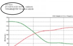
 Looks like the difference is in the TEF measurement setup, I see a super LOOOONG time window and one octave smoothing. IMO a properly windowed reflection free 10m outdoor measurement won't need smoothing, this leads me to believe they are cheating as is generally done in audio marketing. Probably the same reason the cabinet drawings were exposed - so marketing could showoff at a trade show. 🙄
Looks like the difference is in the TEF measurement setup, I see a super LOOOONG time window and one octave smoothing. IMO a properly windowed reflection free 10m outdoor measurement won't need smoothing, this leads me to believe they are cheating as is generally done in audio marketing. Probably the same reason the cabinet drawings were exposed - so marketing could showoff at a trade show. 🙄So obviously I must be missing something,
Note that there is no frequency band stated for the claimed efficiency. So you are completely correct in stating that a box with the same form factor is incapable of being as efficient ( 105db/watt ).
Note that there is no frequency band stated for the claimed efficiency. So you are completely correct in stating that a box with the same form factor is incapable of being as efficient ( 105db/watt ).
Checking this pdf you can see that the 105dB@1W are not simply cherry picking the highest spot, because doing that you even get 109dB@1W. But the Danley white paper on teir measurement states that their sensitivity figures are averaged over the passband, and in the graph in the previous pdf you can also see that the stated efficiency is reached as low down as 50Hz, with 40Hz being -3dB compared to that.
I've been pondering these missing 3dB, and I recalled jbell's talking about directivity in TH's. Seeing as hornresp only calculates the total power response, and not the local intensity response (except for 1 segment flhs), i wonder if that directivity would account for +3dB on axis...
Hi
Actually the specs are Voltage based, not an imaginary Watt;
http://www.danleysoundlabs.com/danley/wp-content/uploads/2012/01/DANLEY-SPECIFICATIONS.pdf
A response curve and impedance curve is also given so that one can see the sensitivity at a frequency of interest, its not just one number.
http://www.danleysoundlabs.com/danley/wp-content/uploads/2012/04/TH118-spec-sheet.pdf
Best,
Tom Danley
What I said is: The DSL subs have 108dB @ 2W. The best I can muster is 105dB @ 2W (4V in 8Ohm), which is the same as 102dB @ 1W.
I challenge anyone to come up with a Hornresp design that does 105dB @ 1W, or 108dB @ 2W for the range down to 40Hz. Short of making a 4m long, 2m wide fullsize horn, I don't think it's possible. So obviously I must be missing something, because I hardly believe that DSL would be lying.
What I said is: The DSL subs have 108dB @ 2W. The best I can muster is 105dB @ 2W (4V in 8Ohm), which is the same as 102dB @ 1W.
So am I to read that the true one watt efficiency of the DSL subs are 102db/watt? As in equivalent voltage of 2 volts into a nominal 4 ohm load, or if you are using a nominal 8 ohm driver 2.83 volts?
Because that number I can believe.
Second question has to do with windowing and smoothing. I to have looked at the published TEF graphs and have the same opinion of very long windowing and smoothing with a wide brush.
I applaud the use of 28.3v as a reference as it removes alot of ambiguity..... however even in the latest published spec that Tom just referenced. http://www.danleysoundlabs.com/danley/wp-content/uploads/2012/04/TH118-spec-sheet.pdf
The Text says 28.3V at 10M -- TEF graph says 100watts at 10M...
It's that pesky confusing watts and volts in the same spec page that kinda throws folks.
The Text says 28.3V at 10M -- TEF graph says 100watts at 10M...
It's that pesky confusing watts and volts in the same spec page that kinda throws folks.
Attachments
Last edited:
Hi
Actually the specs are Voltage based, not an imaginary Watt;
http://www.danleysoundlabs.com/danley/wp-content/uploads/2012/01/DANLEY-SPECIFICATIONS.pdf
A response curve and impedance curve is also given so that one can see the sensitivity at a frequency of interest, its not just one number.
http://www.danleysoundlabs.com/danley/wp-content/uploads/2012/04/TH118-spec-sheet.pdf
Best,
Tom Danley
Hi Tom,
good to see you still reading here, in the years I've been on this forum, I've seen you intersperse quite a few gems of knowledge amongst your posts, and I appreciate that - thank you.
I am aware of the voltage base of your specs, and applaud that as well, though I can understand you would want to clarify that for anybody reading.
Also the decision to use 28.3V at 10m instead of 2.83V at 1m seems a reasonable idea, as it definitely puts you in the far field of the sub, and well away from any near field effects.
The reason why I myself mentioned the ambiguous wattage spec, is because you measure a "nominal 4Ω" load, or in other words a minimal impedance of 3Ω (as I can't find an impedance sweep, I'm guessing around 2.5Ω DC Re) using a 28.3V signal, which corresponds to a lot more than 100W throughout most of the bandwidth of the speaker.
This is not a problem as such, seeing as you state both impedance and voltage clearly, so one can adapt to such.
For fair comparison IMO, one should measure an 8Ω design at 40V/100m or 4V/1m, the latter of which would correspond to the hornresp input. But even accounting for this power difference due to impedance, I still can't manage to simulate these 108dB/2.83V/1m in any way. Not with any existing driver I've tried, not with changing the specs to make some kind of ideal imaginary driver.
I am kind of disappointed that so much info about the DSL designs have leaked, it seems both the driver and the fold pattern are known, I liked it better when they were just a mystery box that could do 108dB@2.83v/4Ω/1m, and there was still the notion, that by changing some parameter around, you could still tickle out an extra 3dB somewhere.
Now however, the main question for me seems to be how to explain the discrepancy between hornresp simulations and measured SPL curve.
If I can find a large enough field, I think I'll do some polar plots of my tapped horn, that might offer some insight. Might be a bit tricky in the city though, so if anybody wants to beat me to it, feel free.
- Home
- Loudspeakers
- Subwoofers
- TH-18 Flat to 35hz! (Xoc1's design)