Thienchay, nice spacing you got there, it looks like you are using different parts is it a modified version? any plans on sharing the bottom artwork for toner transfer?😛
Hi all!,
I wonder if anyone of you had a clearer resolution of the pdf file for DIY share, using Detex IRS900, I have the Detex artwork but I don't think it is going to be successful on laser toner transfer, the image is so poor 🙁
Hi 🙂
This is my PCB file .
Attachments
Hey everyone, watch this topic recently and after a week I built myself a Class D amplifier
Amplifier is functional but the problem is that heat the transistors of the differential and constant current generator.Heat to 55-60 degrees.
I used 4x2N5401.
Mention that the amplifier was tested at a voltage 2x45Vcc
Finally amplifier will work on 2x63Vcc
This amp I will use an active subwoofer 300W/4R.
I apologize for linguistic mistakes, do not know English.
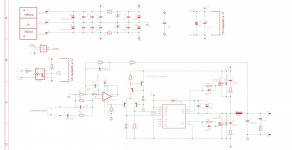
Schematic is here.
Amplifier is functional but the problem is that heat the transistors of the differential and constant current generator.Heat to 55-60 degrees.
I used 4x2N5401.
Mention that the amplifier was tested at a voltage 2x45Vcc
Finally amplifier will work on 2x63Vcc
This amp I will use an active subwoofer 300W/4R.
I apologize for linguistic mistakes, do not know English.
Schematic is here.
Attachments
Anyone willing to make me 2 pcb´s from post 2101,as I don´t have the equipment.
I will pay for the pcb´s.
I will pay for the pcb´s.
thanks thienchay. what about the schematic?
Hi
I not yet had time to do it ,but i think can be confident in this schematic and layout .
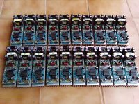
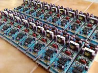
I draw the PCB Layout when looking at pictures of them (Detex Audio) , i see they produce a lot , so i think can confident .
This is some pictures of Detex Audio .
Attachments
![DSCN3272 [Desktop Resolution].JPG](/community/data/attachments/265/265742-159afeed3571cb0c7fd6354cec1446b1.jpg?hash=FZr-7TVxyw)
![DSCN3273 [Desktop Resolution].JPG](/community/data/attachments/265/265746-1e97394cc2f88388002ad686ea8a9e2d.jpg?hash=Hpc5TML4g4)
![DSCN3283 [Desktop Resolution].JPG](/community/data/attachments/265/265753-39fce68f501f0e2f58b76e09a10bec07.jpg?hash=Ofzmj1AfDi)


yeah andrew,
try using higher value for the output inductor, my last test with ejtagle's circuit, i used about 180uH inductor, it gives more punchy sound...... more kick shall i say and one more thing some noise were gone.
try using higher value for the output inductor, my last test with ejtagle's circuit, i used about 180uH inductor, it gives more punchy sound...... more kick shall i say and one more thing some noise were gone.
andrew,
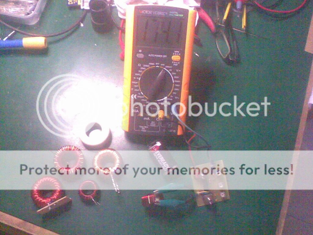
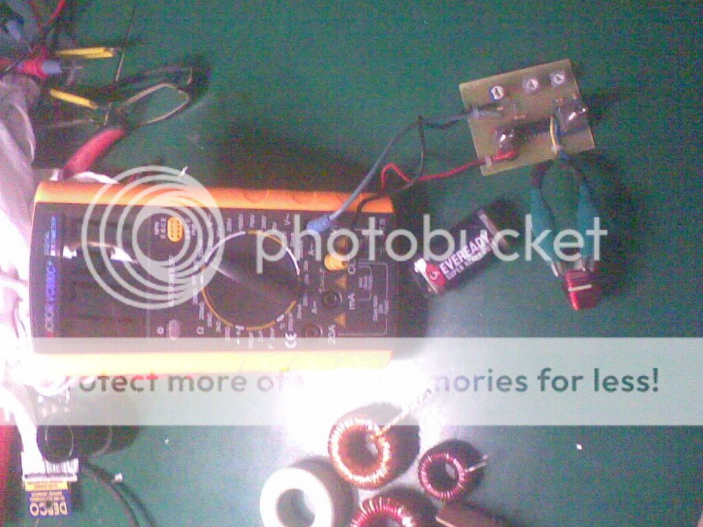
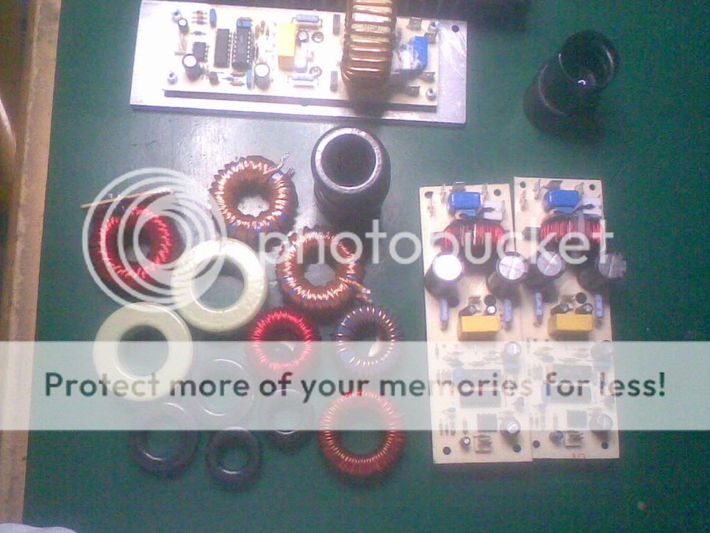
this is the one i used for ejtagle circuit, almost 180uH, 50turns #18 wire 27mm OD for the core, but it was factory wound core. a friend charge me a couple of bucks for the windings, he had a small company dealing with transformer.
thanks to mr. tagle for his circuit, i learn a lot of basics from this...
Hi 🙂
This is my PCB file .
thienchay! you are very helpful...😉 One more thing I see you are using 1N5819 (schottky barrier rectifiers) and 27ohms gate resistors (original was 10ohm). What type of MosFET are you using and at what rail voltage?...
Cheers!😎
thienchay! you are very helpful...😉 One more thing I see you are using 1N5819 (schottky barrier rectifiers) and 27ohms gate resistors (original was 10ohm). What type of MosFET are you using and at what rail voltage?...
Cheers!😎
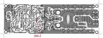
I'm used IRFP460 , schottky Diode is better , and R gate i using 22 ohm 🙂
Sorry All , diode boostrap is FR207 or Diode has Vrrm >= Vcc .
And this is my last check .
Attachments


- Home
- Amplifiers
- Class D
- UCD 25 watts to 1200 watts using 2 mosfets