
Please do not buy these trim pots. The pin spacing is wrong for the boards. 
Is this the trimmer Nelson uses?
3386F-1-501LF Bourns Inc. | 3386F-501LF-ND | DigiKey
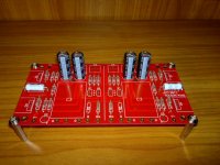
Just one more comment about the board.
For people wanting to use polypropylene capacitors, you have to use axial caps.
Radial (block) caps won't fit.
For people wanting to use polypropylene capacitors, you have to use axial caps.
Radial (block) caps won't fit.
Another comment.
Panasonic 3W ERG metal oxide resistors have steel leads and end caps (ie magnetic).
I thought they were meant to be non-magnetic.
EDIT: Need to order S not F. F has iron leads
EDIT EDIT: Even the S series still has iron end caps. So they are still magnetic
Panasonic 3W ERG metal oxide resistors have steel leads and end caps (ie magnetic).
I thought they were meant to be non-magnetic.
EDIT: Need to order S not F. F has iron leads
EDIT EDIT: Even the S series still has iron end caps. So they are still magnetic
Last edited:
Just one more comment about the board.
For people wanting to use polypropylene capacitors, you have to use axial caps.
Radial (block) caps won't fit.
For people wanting to use polypropylene capacitors, you have to use axial caps.
Radial (block) caps won't fit.
This one looks like it has the right lead spacing
3386P-1-501LF Bourns Inc. | 3386P-501LF-ND | DigiKey
3386P-1-501LF Bourns Inc. | 3386P-501LF-ND | DigiKey
I don't like trim pots. They are necessay sometimes. Ussually you can sit on them and play for a while to get a good idea of the long term stability, and then replace with a fixed "Audiophile" type component. Or, I use Vi$hay metal foil trim pot$. The long one$ Ive u$ed are black. The $quare one$ on my B3 are green.
The cap issue is interesting. Ive got a few to try that should be of a sufficient voltage breakdown but fit the footprint. and a big poly similar to what N.P. used. what was that big Pass cap?
The cap issue is interesting. Ive got a few to try that should be of a sufficient voltage breakdown but fit the footprint. and a big poly similar to what N.P. used. what was that big Pass cap?
what was that big Pass cap?
The original BA-3 article shows a photo of the cap in question. The markings on it say its a Claritycap PWA series.
Graeme
Yep, I'm not sure what series I have at the moment. Can't go look, but I got something like that, that fit. Not outrageously expensive as I recall...
I might just have one a couple of those Axon's too!
Actually I'm waiting to try a more direct coupling method, without the cap. Just the tl431 between the MOSFETs We'll see...
I might just have one a couple of those Axon's too!
Actually I'm waiting to try a more direct coupling method, without the cap. Just the tl431 between the MOSFETs We'll see...
Last edited:
Actually I'm waiting to try a more direct coupling method, without the cap. Just the tl431 between the MOSFETs We'll see...
Keeping them separate allows you to adjust the bias through the 2013/313's independently from setting the operating current through the 431. Plus, I don't know how the 431 would feel about 45+ ma running through it. Would need to check on that.
You could consider a traditional discrete Vbe multiplier.
Graeme
Last edited:
It would mean different boards, but consider other biasing arrangements than tl431. Ba3 needs cap for more experimenting than coupling reasons as I remember. Helps with stability and I don't know away around that without feedback.
flg,
Check out the A75 part 1 article on the passdiy site and look at fig. 9.
You could try putting your tl431 between the 2013 and 313 then use two 620 or 680 ohm resistors to ground from each drain in place of R13 in the BA-3 FE. Like R24 and R25 in the A75. I would put a good sized cap around the 431 too. That keeps the front end bias/gain adjustment separate from the output bias and keeps the current through the 431 down - and no coupling caps.
If it was me, I'd give it a shot.
gl
Last edited:
I hadn't used a tl431 at that high a current before either but, I went and looked. it should do it. Maybe a little heat sink is in order...
as for the resistors to GND, I've seen both ways???
As for the adjusting output bias, it would still be with the TL pot. The 2013/313's bias would still be the pot bypassed by the cap in th JFET darins.
😀
as for the resistors to GND, I've seen both ways???
As for the adjusting output bias, it would still be with the TL pot. The 2013/313's bias would still be the pot bypassed by the cap in th JFET darins.
😀
I looked at the 431 data sheet too. Assuming 9V across the 431 and 45ma through it gives you 405 mw being dissipated. That's higher than I like to run a TO92, especially if it's in an enclosed space.
The pot in the JFET drains doesn't set the bias in the 2013/313 stage.
The big similarity between the BA-3 FE (and BA-3b) and the A75 FE is that they're designed to be run open loop if that's your thing.
The resistor(s) to ground would carry the 2013/313 bias current so that the 431 doesn't have to.
I think you have a cool idea there of trying to simplify the interface between the BA-3 FE and the crippled F4 or BA output section.
gl
Last edited:
- Home
- Amplifiers
- Pass Labs
- Burning Amp BA-3b (Balanced)