Be careful, from what I read, you need to configure the VFD before firing up the spindle.
Apparently the parameters can be so wrong that the smoke comes out...
After it's set properly, they are apparently all good.
Apparently the parameters can be so wrong that the smoke comes out...
After it's set properly, they are apparently all good.
I can't help but feel this is turning into more of CNC thread than a speaker one but what the hell I'm sure there'll be some audio related stuff in here one day.
On the general topic of WMTMW Cabinet Construction for the World's Greatest Speaker(WGS). Electronic delay allows minimum M-T and M-M spacing since physical steps used to time align speaker positioning that lengthen these distances are not necessary.
If we assume that the WGS will have an analog or digital electronic crossover capable of time delay, would the best cabinet have an essentialy flat front baffle with the shortest M-T-M spacing plus diffraction minimization from large radius round edges next to the MTM?
Attachments

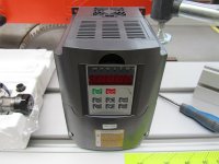
Kress has been ditched before even firing it up. Have now gone ahead and ordered one of the chinese 3HP watercooled spindles and vfd.
Will be very interested to see how that goes. Could well be tempted if it looks decent.
On the general topic of WMTMW Cabinet Construction for the World's Greatest Speaker(WGS). Electronic delay allows minimum M-T and M-M spacing since physical steps used to time align speaker positioning that lengthen these distances are not necessary.
If we assume that the WGS will have an analog or digital electronic crossover capable of time delay, would the best cabinet have an essentialy flat front baffle with the shortest M-T-M spacing plus diffraction minimization from large radius round edges next to the MTM?
Delay only works on-axis.
Even with a digital crossover, I'm going for the middle ground. Some tweeter recessing, but not the full amount (30-40mm?) required for on-axis time alignment.
Also, with a CNC, there is NO WAY IN HELL that I am whacking my drivers on a flat baffle!!! 😀
I'm going nuts. I have an angled baffle (like focal), with a curved edge + rounds on the corners. I have a tweeter baffle with Audiom style bumps, and another tweeter baffle which is a waveguide in the works.
CNC opens up the possibilities.
Hey guys,
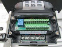
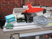
I've begun tearing down the cnc machine in preparation for a bunch of upgrades. The first area I'm going to tackle is the electronics. The bits that were in there were OK but there was room for improvement so I've ordered some cool DSP based digital stepper drivers and these do all sorts of crazy things to help smooth out the stepper motors and try to negate their short comings. The goal here is to try to make a stepper perform like a servo without their cost or peculiarities. The power supplies are to be upgraded from regulated types to unregulated to allow for higher voltage and more speed. I'll take the opportunity to rewired everything too as I don't like the idea of using unscreened cables, especially with the vfd.
Here's how things look right now:

Nearly everyone I've spoken too has said I need home switches on at least the x and y axis so I picked a few up and will be adding these to the machine.

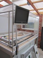
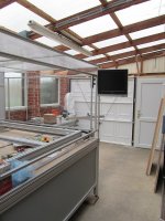
I've been struggling to come up with somewhere to keep the PC that doesn't mean taking up more valuable workshop space then after looking at what others did it seemed really obvious to integrate it into the machine. There's loads of space in the base for the PC and hanging the monitor and keyboard from the framework is very simple. Another nice touch with going this route is the ability to spin the screen around so you can see what going on from whichever of the two sides of the machine you might be watching from. The hand controller is mounted just below the screen.


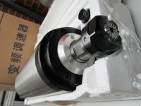
The VFD/Spindle arrived today. First impressions are that the spindle is much more substantial than the Kress. It easily weighs 3 times the amount. Should be a huge upgrade here. Need to get me an ER20 collet set now.


I've begun tearing down the cnc machine in preparation for a bunch of upgrades. The first area I'm going to tackle is the electronics. The bits that were in there were OK but there was room for improvement so I've ordered some cool DSP based digital stepper drivers and these do all sorts of crazy things to help smooth out the stepper motors and try to negate their short comings. The goal here is to try to make a stepper perform like a servo without their cost or peculiarities. The power supplies are to be upgraded from regulated types to unregulated to allow for higher voltage and more speed. I'll take the opportunity to rewired everything too as I don't like the idea of using unscreened cables, especially with the vfd.
Here's how things look right now:
Nearly everyone I've spoken too has said I need home switches on at least the x and y axis so I picked a few up and will be adding these to the machine.
I've been struggling to come up with somewhere to keep the PC that doesn't mean taking up more valuable workshop space then after looking at what others did it seemed really obvious to integrate it into the machine. There's loads of space in the base for the PC and hanging the monitor and keyboard from the framework is very simple. Another nice touch with going this route is the ability to spin the screen around so you can see what going on from whichever of the two sides of the machine you might be watching from. The hand controller is mounted just below the screen.
The VFD/Spindle arrived today. First impressions are that the spindle is much more substantial than the Kress. It easily weighs 3 times the amount. Should be a huge upgrade here. Need to get me an ER20 collet set now.
Attachments
-
 cncscreen01.JPG108.3 KB · Views: 948
 -
 cncscreen02.JPG111.8 KB · Views: 966
 -
 spindlevfd03.JPG82.1 KB · Views: 930
 -
 spindlevfd04.JPG114.9 KB · Views: 925
 -
 spindlevfd02.JPG81.4 KB · Views: 931
 -
 ctrlbox01.JPG103.3 KB · Views: 944
 -
 homingswct01.JPG96.4 KB · Views: 926
 -
 spindlevfd01.JPG99 KB · Views: 927
What Stepper Drive was fitted? Gecko 540?
I'm interested in the details of the DSP based drives.
And...
No one can accuse you of under-doing things 😱
I'm interested in the details of the DSP based drives.
And...
No one can accuse you of under-doing things 😱
What Stepper Drive was fitted? Gecko 540?
I'm interested in the details of the DSP based drives.
And...
No one can accuse you of under-doing things 😱
Hi Mark
The drivers were an odd mix of 50v and 80v models. On the Y and Z they'd used two of these:
Stepper Motor Driver 4.5A, 50V CNC Microstepping
Then for the X axis with dual motors they'd used a pair of these:
Stepper Motor Driver 6.0A, 80V CNC Microstepping
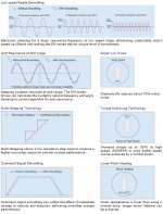
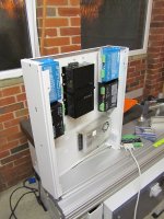
I'm no expert but I'm told those drivers are pretty good however its not a great idea mixing and matching different drivers. I think they'd done that to keep costs down and whilst it would work fine its not going to get the most out of the machine hence why I've done away with them and starting from scratch using these:
AM882 Digital driver with stall detect
They're DSP based and have stall detection to let you know if you missed a step. You can also rig up your PC to the drivers and then, using the supplied software, fine tune parameters or let the auto configure do it instead.
There's a neat overview from the manufacturer's website that explains the main upshots:
The sentiment amongst others who are using these is that they achieve the same low speed smoothness and accuracy you get from servo's and operating noise from the steppers is drastically reduced.
Attachments
Hi Mark
I'm no expert but I'm told those drivers are pretty good however its not a great idea mixing and matching different drivers. I think they'd done that to keep costs down and whilst it would work fine its not going to get the most out of the machine hence why I've done away with them and starting from scratch using these:
Not true at all. Ideally the driver, motor, screw, etc. would be matched to the axis it's mounted on. If they're using larger higher inductance motors on the x for example, the higher current higher voltage drives are totally appropriate. But the Y and Z axes are much lower masses to move, so the drives could be smaller. Without reverse engineering the entire machine it's impossible to say those were the correct decisions, but it's certainly possible.
Not true at all. Ideally the driver, motor, screw, etc. would be matched to the axis it's mounted on. If they're using larger higher inductance motors on the x for example, the higher current higher voltage drives are totally appropriate. But the Y and Z axes are much lower masses to move, so the drives could be smaller. Without reverse engineering the entire machine it's impossible to say those were the correct decisions, but it's certainly possible.
The dual axis (X) had the larger 80v/6A drivers and these had the most work to do as they move the entire gantry. The motors on the X and Y are Nema23 4Nm models and the Z is a Nema23 3Nm. The ballscrews for the Y and Z are identical, however those on the X have a higher number of turns per distance unit.
I had a visit from a friendly CNC'er who lived nearby and he gave the machine a look over which is where this point came up. I did some more research and couldn't find any cases where people mixed drivers.
What DIY cnc builders do is not always an indication of what's required and what the most economical way to build a properly functioning machine is. They are very fond of overkill in my experience, and it can make life easier. You throw some big motors and drivers at it and don't worry about calculating out the exact torque required to produce the acceleration you want and the required cutting force. There's also typically not a large price difference between a small and large motor driver that hobbyists are buying, so most would pick to get all of the same type for simplicity and overkill once again. A professional machine builder might optimize their electronics more to save costs where they won't get any added benefit. That could add up over time. I can tell you that I'll be using different size motors on the mill I'm working on because that's what will work well - dual 12Nm servos on the Z and 38Nm on the X and Y. I'll be using the same drivers on all axes because I can't find any bigger ones that are in my price range, but I've balanced the drivers' current limits against the peak and continuous current limits for the various motors to get the performance that I need. I also get a quantity discount on 5 drives (5 for the price of 4), so I'll have a spare or one to use to make a 4th axis.
Possibly but I think in general corners have been cut to keep the machines cost down. That's not me putting down the manufacturer but for the price I paid something had to give. Its just economics and because the electronics are probably the single most expensive part of the machine it figures if your going to make savings then this is where you'd stand to reap the biggest rewards.
Its not just the electronics though. I've gone over the machine and there's a few area's that would benefit from attention and these are the main offenders:
I plan to fix all of those.
Good news is the machine is a great base to build upon and with some improvements will be quite capable. I estimate I'll have to spend another £1000 over the purchase price to get it to where I'd like which still makes it high on value compared to out right buying. The downside is I've ended up DIY'ing and spent a lot of time not cutting.
Its not just the electronics though. I've gone over the machine and there's a few area's that would benefit from attention and these are the main offenders:
- Lack of limit/home switches. This to me seems like a silly cost saving measure because they cost very little (I paid £20 for 6 including the connectors and cable)
- Substituting round rail clamps, fitted with cheap and unsuitable 6100Z bearings, as ballscrew supports. These should be bonafide FK/FF or BK/BF type supports with radial bearings. Without these long term accuracy of the machine is in question. I pulled the manufacturer up about this and they're supplying the correct parts which is good but should have been done in the first place.
- Omitting shielded cabling for stepper wiring. Possibly not a big deal but often with a VFD and switching signals there's a great deal of interference that can mess with switches and motors causing errors. You could argue about this one but decent machines will have shielded.
- Electronics that don't extract the most performance out of the motors they're driving. Cheap regulated SMPS that are underspec'd on Amps and don't deal very well with back EMF most often generated when steppers decelerate.
- Lack of bracing on the table with only a single center support beam. If you plunge at the right spot I've no doubt you'd get some flex of the MDF bed because its under supported.
- Supplied with a light duty spindle that will wear quite quickly with any serious use. I can't say too much about this because, at that time, in my ignorance I choose that option thinking it would be OK. Still it would have been nice if the manufacturer told me it wouldn't really do what I wanted.
I plan to fix all of those.
Good news is the machine is a great base to build upon and with some improvements will be quite capable. I estimate I'll have to spend another £1000 over the purchase price to get it to where I'd like which still makes it high on value compared to out right buying. The downside is I've ended up DIY'ing and spent a lot of time not cutting.
Last edited:
shin,
have u considered testing sb acoustic satori? it seems they are on par with AT18H.
cheers
henry
have u considered testing sb acoustic satori? it seems they are on par with AT18H.
cheers
henry
Hey Hezz
Its PC controlled via Mach and parallel port.
This seems to work OK although I might get one of the USB based controller boards eventually so the trajectory planning and so on is off loaded from the PC and it acts as a simple data source rather than a controller. That way I can then use the PC for music/web surfing/CAD in the workshop without fear of interfering with the machining processes.
The PC I use is a Dell desktop with a 3Ghz Core2duo cpu, 2Gb ram and a small 40Gb SSD with XP installed. Very pedestrian compared to more modern offerings but its more than fine for Mach. The annoying thing about Mach is its reliance on the parallel port. Any half decent modern motherboard doesn't bother with this ancient tech anymore so going USB for the controller will allow for a better equipped PC in the workshop which can only be a good thing when it comes to Solidworks as it'll eat whatever resources you throw at it.
Thanks for the tips on the CAM and g-code side of things. I got a copy of Vectric VCarve bundled with the machine and this doesn't look too bad from playing around. It'll do most of what I want but its not suited for 3D and so I will need to upgrade at some point. It'll get me going for now though and it was free.
Tbh I'm keeping an ear to the ground on ebay and hoping to find an older copy of MasterCAM or SolidCAM for little money. They're rare but do pop up every so often. I'm not fussed about an old version as even these are feature rich and the lack of tech support doesn't put me off either.
Shin, sounds like that software package you have is a pretty good start. I researched it a little and was pretty impressed with what I saw. I'm looking forward to seeing your CNC upgrades. That new spindle alone should make a big difference. Probably has much more substantial bearings and horsepower. The reduced vibration and extra power will make a big improvement in cutting. And of course with CNC you really need to be able to control the speed of the spindle to get the best cutting. X and Y limiting switches are also a very good idea. Very easy to mess up a machine like that with aluminum frame by over traveling on one of those axis.
If you send me a private e-mail I can get you in touch with some older versions (5-6 year old), CAM packages for next to nothing. Good luck. Your machine and workshop is really nice.
Hezz
Last edited:
Shin, sounds like that software package you have is a pretty good start. I researched it a little and was pretty impressed with what I saw.
I've been playing around with Vectric this past week or two and I'm happy with it. Its easy to use but I guess this comes from the fact that its not over burdened with advanced milling features and instead keeps things simple. You've basically got profiles, pockets and drilling along with some pseudo 2.5D milling paths that seem to work well although there isn't much in the way customisation and so you have to trust the program to be smart enough to do a decent job which isn't always the case.
I'm looking forward to seeing your CNC upgrades. That new spindle alone should make a big difference.
Yep, I'm confident the new spindle will be a huge upgrade over the original Dremel style one. Its double the HP and the vfd will ensure the majority of that torque is delivered even right down to 6000rpm.
If you send me a private e-mail I can get you in touch with some older versions (5-6 year old), CAM packages for next to nothing. Good luck. Your machine and workshop is really nice.
Hezz
Thanks. I'll PM my email.
2.5 Axis CAM
When it comes to 2.5D CAM you can't beat HSMXpress. It is free for any SolidWorks user!
It even includes world class machine communication software
Check it out HSMXpress | HSMWorks • Integrated CAM for SolidWorks
When it comes to 2.5D CAM you can't beat HSMXpress. It is free for any SolidWorks user!
It even includes world class machine communication software
Check it out HSMXpress | HSMWorks • Integrated CAM for SolidWorks
Hey guys,
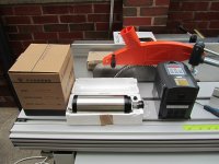
Most of the replacement parts have arrived now and installation has begun.


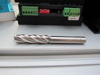
And my first end mill! Its a 14mm diameter flute and 12mm shank with overall length of 120mm. Perfect for cutting the thick baffles.

Most of the replacement parts have arrived now and installation has begun.
And my first end mill! Its a 14mm diameter flute and 12mm shank with overall length of 120mm. Perfect for cutting the thick baffles.
Attachments
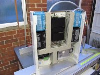
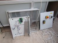
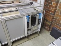
All wiring within the control box now complete with the exception of the relays. Next up soldering the stepper and home switch cabling in to the connector panel that breaks out on the top side of the machine (you can see the panel in laid up against the bed in the photo). After this its onto rewiring all the top side with shielded cabling and installing home switches.
Also in the photo if check left next to electronics enclosure there's a panel. This will be removed and a door fitted to house the PC.

Also in the photo if check left next to electronics enclosure there's a panel. This will be removed and a door fitted to house the PC.
Attachments
- Status
- Not open for further replies.
- Home
- Loudspeakers
- Multi-Way
- Apollo Construction Diary