Yes, there are basically 4 resistors and a trimpot that set the currents on the JC-2, and every version I have seen, starting from the "original" one (JC could say if it is indeed the original) until the last one seem to be different.
So it's difficult to say which to go for. The circuit being a folded cascode makes it even more difficult.
Reducing currents in order to get things cooler might be better for the parts, but certainly not for the audio performance.
Should I go back to the original values (100 & 20 ohms)?
The JC-2 clone apparently choose approximately what Borbely used on his EB604 (post #45): 1K5 & 332 ohms. But EB's second stage were jfets, so currents should be small, me thinks.
Where do I start?
I kind of went trough the same problem, too much information and too many schematics and variants of the JC-2. It came down to tubeshunter and jim's_audio on eBay. Then it came down to the eBay feedback score. Maybe this helps.
I kind of went trough the same problem, too much information and too many schematics and variants of the JC-2. It came down to tubeshunter and jim's_audio on eBay. Then it came down to the eBay feedback score. Maybe this helps.
Paralleling resistors on the lower side of the pcb should be an easy way to try higher current options.
Some comments from Mr Curl should throw some light over this resistor dilemma.
On post #157 he says that there should be at least 1.5v across the load resistors, and suggests at least 150 ohms instead of 100 for the Toshiba Fets.
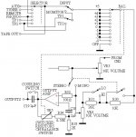
So the question now turns to the emitter resistors on the output stage, which are part of the folded cascode too.
There are also two trimpots that need setting too, which should be explained on the kit.
On post #157 he says that there should be at least 1.5v across the load resistors, and suggests at least 150 ohms instead of 100 for the Toshiba Fets.
So the question now turns to the emitter resistors on the output stage, which are part of the folded cascode too.
There are also two trimpots that need setting too, which should be explained on the kit.

Which FETs are used in the actual circuit ? The current through them appears to be 1.3 - 2 mA (a bit on low side, but probably chosen to allow for a wide range of FET grades).
The current of the output stage seems to be somewhere between 12 and 20 mA, which is OK IMHO.
The current of the output stage seems to be somewhere between 12 and 20 mA, which is OK IMHO.
2V to 3V of Vdrop across that 1k5 gives a total current in the output+jFETs of ~14mA to 24mA.
If the Left side jFET currents are only 1.3mA to 2mA, then the output stage currents are in the range 12.7mA to 22mA.
It looks like LR5 value needs a lot of experimenting. That may result in LR2 dropping a bit.
If the Left side jFET currents are only 1.3mA to 2mA, then the output stage currents are in the range 12.7mA to 22mA.
It looks like LR5 value needs a lot of experimenting. That may result in LR2 dropping a bit.
Hi there,
The kit is carried by us.
I am a bit awkward to respond on a non-commercial thread but hope a short reply can facilitate the discussion.
We are using matched 2SK246BL and 2SJ103BL. Idss between 6mA to 8mA are selected. Same type matching is good to 3%. Complementary type matching is about 10%.
The kit is carried by us.
I am a bit awkward to respond on a non-commercial thread but hope a short reply can facilitate the discussion.
We are using matched 2SK246BL and 2SJ103BL. Idss between 6mA to 8mA are selected. Same type matching is good to 3%. Complementary type matching is about 10%.
Slightly starved version. Better to run higher current.
Should we go back to the original values?
That is: 100 to 150R for LR2/LR5 and 20R for LR3/LR6?
Hi there,
The kit is carried by us.
I am a bit awkward to respond on a non-commercial thread but hope a short reply can facilitate the discussion.
We are using matched 2SK246BL and 2SJ103BL. Idss between 6mA to 8mA are selected. Same type matching is good to 3%. Complementary type matching is about 10%.
JIMSAUDIO, welcome and thanks for chiming in.
There's a quite similar thread discussing the JC-2 preamp, where I'm rising other questions:
http://www.diyaudio.com/forums/solid-state/10160-need-build-jc-2-preamp-37.html#post2884040
These are not threads opened by me, so I can't ask to join them. But I also do not want to ask similar questions for the JC-2 preamp on both threads.
This thread seems to be concentrated right now on the Line Amp. But I think the other one is also considering the whole preamp project, including external parts (never mentioned here) and a phono preamp.
The parts I'm talking about are here around the Output Amp.
On the newer JC-2 versions there is LR01 (3K3) and LR4 (10K), which are the gain resistors. On the original JC-2 those gain parts were external, involving a balance switch and also a 2uF capacitor.
Should we disregard those parts on this project?
Attachments
...
Should we disregard those parts on this project?
Probably disregard them in terms of the discussion of the JC-2 design and its variants as has been the topic so far...JMO
Probably disregard them in terms of the discussion of the JC-2 design and its variants as has been the topic so far...JMO
Not quite. Two components are important and what better values to use should be mentioned:
1) Input volume pot.
2) Output capacitor (if any).
You will find ALL Parasound power amps and preamps made this way for the last 15 years.
.
If only parasound power amps sounded good!
I owned a halo a51 that I bought based on reviews ive read- horrificly high noise floor, floppy bass- slow sounding, lack of general detail. Id have thrown it away if it didnt cost so much.
Sold it for twice what I payed though

I Am OK Very Good Sound
An externally hosted image should be here but it was not working when we last tested it.
An externally hosted image should be here but it was not working when we last tested it.
An externally hosted image should be here but it was not working when we last tested it.
An externally hosted image should be here but it was not working when we last tested it.
Nice work tfender, looking forward to hearing more comments on sound appreciation.
Which transistors did you use?
Which transistors did you use?
Nice work tfender, looking forward to hearing more comments on sound appreciation.
Which transistors did you use?
I Use
2SK170BL & 2SJ74BL and BC546B , BC556B
Nice work tfender, looking forward to hearing more comments on sound appreciation.
Which transistors did you use?
the sound in the overall image that me hears , waste matter greedy omen clean peacefulness , distinctness , , , and , Impack , in frequency low section is the thing that me impresses very , 😀
Good to hear you are impressed... Soon I will build mine starting from a kit...but also have a layout to use the venerable Toshiba 2SK389 and 2SJ109 at the input plus other Toshiba's on the output. The layout includes cap multipliers for each polarity on each channel, as per JC suggestions.
I have all the transistors etc except the PCB which I'm a bit lazy to etch.
cheers, Tony
I have all the transistors etc except the PCB which I'm a bit lazy to etch.
cheers, Tony
Last edited:
- Home
- Source & Line
- Analog Line Level
- Variation on the JC-2 preamplifier