From the very few projects I've completed, I find that the ear is the best instrument for tuning the compensation caps (phase lag especially but also phase lead) once you are within the envelope of good stability.
Thanks everyone for letting me know that the compensation cap can be tuned by ears. Initially I was skeptical even tho all the experts had confirmed the fact 🙂p). But after Bigun mentioning the phase lag thing suddenly I realized 😀
Still, LC has not confirmed about the cap. Small one could be issue, but none couldn't be, as long as it is stable?
You were contemplating some Vbe mult. between the drivers and/or TO-92 DN2540s instead of trimmers, weren't you?
It may be that a Vbe multiplier is required. I can't see the current for the drivers being very stable, and it directly affects output bias in this version. It's not clear to me that a current source, instead of a resistor (plus trimmer) will have much affect on reaching a stable equilibrium. Cascoding the drivers might help by reducing the dissipation.
But I think something else is amiss also, as I see significant distortion in the waveform when driving an 8 Ohm load. With a load, it overshoots, but doesn't settles. With no load, it rings quite a bit. I built it up first without the Miller comp caps. I'm pretty sure it was oscillating. I replaced the drivers, when I added the compensation caps. I'm wondering if oscillation could have damaged the outputs too.
I'm not sure I want to chase this down for the TT version. Maybe Nico's design is the way to go for a simple version of the amp.
Sheldon
The Vbe multiplier mod to test at least, I think. The main issue with the Sziklai and Latfets was the drivers current running and I put the Jfet CCS there for instance. Maybe you got to find another operating current for the drivers to see how it affects ringing?
BTW, can you tell me how much current your input bjts run and if its near between pnp and npn? Drop in mv over their 10R emitter resistor will show.
Member
Joined 2009
Paid Member
The VAS current is very sensitive to the VAS device temperature.
I realized this is a feature of all symmetrical BJT VAS designs - at least those I've seen. I noticed that the Bryston amp I have, which is also a symmetrical VAS, uses large emitter degeneration resistors on the VAS. So I also used large degeneration resistors on the VAS of my TGM5 amplifier. I believe it helps to reduce sensitivity of the VAS current to operating conditions.
It may be that a Vbe multiplier is required. I can't see the current for the drivers being very stable, and it directly affects output bias in this version. It's not clear to me that a current source, instead of a resistor (plus trimmer) will have much affect on reaching a stable equilibrium.
I went through the same issues in TGM5, albeit in Spice simulations. I concluded that the VAS current would not be stable enough to guarantee good output bias without paying some attention to the Vbe multiplier. I ended up using a design from Hagerman. I don't find the output bias as stable as my TGM1 but it appears to do the job well enough. In fact, the amp has been more stable with respect to temperature than I had feared, both bias and dc offset.
I used small compensation caps on both the VAS and the pre-drivers of the Triple output stage.
This topology sounds good, it's worth persevering.
Last edited:
Gareth,
If you use three 1N4148 diodes in series with a 200R pot, you can ameliorate the bias current instability of a sensitive dual VAS configuration, particularly with the J1058/J162 latfets.
Hugh
If you use three 1N4148 diodes in series with a 200R pot, you can ameliorate the bias current instability of a sensitive dual VAS configuration, particularly with the J1058/J162 latfets.
Hugh
Gareth,
If you use three 1N4148 diodes in series with a 200R pot, you can ameliorate the bias current instability of a sensitive dual VAS configuration, particularly with the J1058/J162 latfets.
Hugh
For some reason, 1N400X performs much better than 1N4148 in that situation.
I believe that the reason for the temperature sensitive VAS is the fact that is also current vise dependent on the input-stage, so two thermal issues is playing a role, and as none of them is driven by a CCS, you will run into thermal problems...This circuit sounds fantastic, but needs better household...!! The Salas Jfet is good for the VAS, bur does not solve the input-stage current dependency
Well, you can add two caps in serial with the CR at the mass reference points. It will reduce to 1 the gain of the amp at DC.
Member
Joined 2009
Paid Member
I believe that the reason for the temperature sensitive VAS is the fact that is also current vise dependent on the input-stage, so two thermal issues is playing a role, and as none of them is driven by a CCS, you will run into thermal problems...This circuit sounds fantastic, but needs better household...!! The Salas Jfet is good for the VAS, bur does not solve the input-stage current dependency
My sims also highlighted this. I actually found you can fix this by incorporating a thermistor in the circuit but that seems like a kludge. In the end, I didn't find thermal stability to be an issue. But there's an opportunity still to improve it - but achieving that without spoiling the topology doesn't look trivial.
I believe that the reason for the temperature sensitive VAS is the fact that is also current vise dependent on the input-stage, so two thermal issues is playing a role, and as none of them is driven by a CCS, you will run into thermal problems...This circuit sounds fantastic, but needs better household...!! The Salas Jfet is good for the VAS, bur does not solve the input-stage current dependency
That is why the input stage VR (trimmer) CCSs got to be BF245s as well. One of those variable.
Look alive to the thermal offsets.Guys have to go out, urgently (Friday's eve) .. I'll be back soon 😀
BTW, can you tell me how much current your input bjts run and if its near between pnp and npn? Drop in mv over their 10R emitter resistor will show.
About 2.2mA, with 8ma of driver current, 2.35mA with 12mA driver current. Same for both sides. Thermal drift for inputs is much lower than for the drivers.
Sheldon
Hi guys, me back 😀
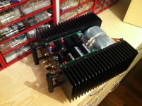
I really like the simplicitiy of the input stage and splitted feedback and all about SSA, so I decided to solve thermal stability issue in a simple manner. Of course one could do it by adding BJT's, OP amps, etc., but than this would become something else. The simplest solution of them all is to put NTC + serial resistor in parallel to 100 uF in feedback bridge. NTC must be thermally coupled with the input pair BJT-s and serial resistor is serving to lock the NTC to be in exact proportion to input's Vbe thermal drift. At the end VAS bias current is stabilized to 10 mA from cold start to any thermal condition there is. 😉
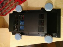
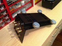
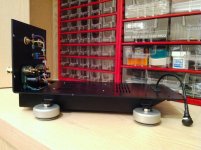
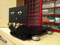
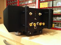
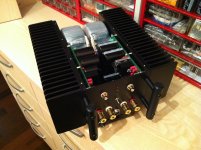
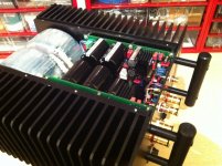
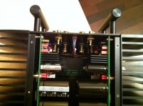
And some pictures to show how SSA BIGBT HP should look at the end. 😎
I really like the simplicitiy of the input stage and splitted feedback and all about SSA, so I decided to solve thermal stability issue in a simple manner. Of course one could do it by adding BJT's, OP amps, etc., but than this would become something else. The simplest solution of them all is to put NTC + serial resistor in parallel to 100 uF in feedback bridge. NTC must be thermally coupled with the input pair BJT-s and serial resistor is serving to lock the NTC to be in exact proportion to input's Vbe thermal drift. At the end VAS bias current is stabilized to 10 mA from cold start to any thermal condition there is. 😉
And some pictures to show how SSA BIGBT HP should look at the end. 😎
Attachments

- Status
- Not open for further replies.
- Home
- Amplifiers
- Solid State
- Simple Symetrical Amplifier