I use one of these, works fine. Just need to be careful to not do it too often...
EDSYN|SS011|ENTLOETGERAET ANTISTATISCH/ TEFLONSPITZE | Farnell Deutschland
EDSYN|SS011|ENTLOETGERAET ANTISTATISCH/ TEFLONSPITZE | Farnell Deutschland
Thank you for the tips.. I already experimented with the solder sucker without positive results... I will try the heated wire 🙂
i got the SMD PPS caps for Michaels Paradise. I am selecting them at the moment.
Ricardo, on what values did you decide for your build ?
Ricardo, on what values did you decide for your build ?
I am using the 6800pF caps and 130k for starters.
As for the 15k I will use 15k // 16k2 and trim the 40.8 cap accordingly.
If it has too much treble (subjectively) I will add some picos to the 13.6nF cap also.
If I feel that the sound is too bass heavy and lacks bite, I will parallel something to the 65kr ... I will let you know.
As for the 15k I will use 15k // 16k2 and trim the 40.8 cap accordingly.
If it has too much treble (subjectively) I will add some picos to the 13.6nF cap also.
If I feel that the sound is too bass heavy and lacks bite, I will parallel something to the 65kr ... I will let you know.
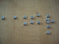
I have now stuffed the SMDs to Michaels board. The values i got are :
Channel 1 : 13,97nF , 41,6nF
Channel 2 : 14,01nF , 41,5nF
The caps all measured slightly high so i assume that my cheep LCR meter errs in the positive direction too, so the values will be somewhat lower in praxis.
Channel 1 : 13,97nF , 41,6nF
Channel 2 : 14,01nF , 41,5nF
The caps all measured slightly high so i assume that my cheep LCR meter errs in the positive direction too, so the values will be somewhat lower in praxis.
I have now stuffed the SMDs to Michaels board. The values i got are :
Channel 1 : 13,97nF , 41,6nF
Channel 2 : 14,01nF , 41,5nF
The caps all measured slightly high so i assume that my cheep LCR meter errs in the positive direction too, so the values will be somewhat lower in praxis.
IMO, the trebble caps are very good.
In your case I would try to use 7650r in series with the 41.5 caps
That can be done by using 15k // 15k6... that way you have Time C = 318.2 (Freq 500.1), very near the ideal 318 (500.5Hz)
Of course.... My meter is ajustable and I use a 0.3% reference cap for that purpose.
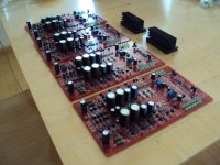
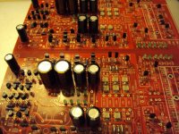
Now I have completed the boards and am working on the case and PSU connections.
Now I have completed the boards and am working on the case and PSU connections.
I checked my meter with reference caps and is measures slightly high but under 1% in all cases. It is amazing that such a cheep meter is so good.
This is how it looks....
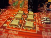
how was the soldering? enough space, good connections? this is my "special" footprint so i would like to know if it works.....
The caps solder easy. I put a small "point" of solder on one pad, then i place the SMD cap and push it down where it should be. Then i heat the "point" or call it "spot". The cap is notw fixed to one side, although only in a little space. Then i solder the other side and then i finish the side where the "spot" fixing is. I make sure that the solder joints look shiny and give a "minimal" surface that looks like the roof of the Olympia stadium in Munich.

Just completed all connections and fired the rig.
Right Channel:
Shunt outputs are
+24V (I can adjust it with the trimmer)
-35.7V (I can NOT adjust it)
Input offset -2.5mV to -1.9mV oscilating (When I switch off, this offset starts rising until it reaches 30mV and than goes down)
Output offset Wild oscilation between +12 and -10V
On switch on, opamp leds light imediately... after a while the negative shunt leds light up and 5 seconds latter finally the positive shunt leds light
Left channel:
Shunt outputs are
+21.4V (I can not adjust it and the leds are very dim)
-24V (I can adjust this value with the trimmer)
Input offset: 9.6V steady
Output offset: 12.75V steady
Leds on the opamp flicker.
This is going to be harder than I was hopin for 🙁
That is what i told. Speed is not helping here. I am sorry.
On the other hand it proved to work and you will find out. I would start with the PSU.
On the other hand it proved to work and you will find out. I would start with the PSU.
Ricardo,
It's one of the diy-mysteries, why 90% of the non-working builds are regulators. From these faulty regulators, 90% are shunts...
I hope you did not connect the regs to the rest yet. Work patiently, it will be worth it. We are with you! 😉 Now have a drink or two...
Rüdiger
It's one of the diy-mysteries, why 90% of the non-working builds are regulators. From these faulty regulators, 90% are shunts...
I hope you did not connect the regs to the rest yet. Work patiently, it will be worth it. We are with you! 😉 Now have a drink or two...
Rüdiger
Yes, the -35,7V can destroy parts of the circuit and it will of cause screw up the servo badly.
On the other hand modern parts are very robust so i assume they survived.
On the other hand modern parts are very robust so i assume they survived.