The measurement you've shown in post 33 looks much more reflection free than your Arta measurement around the same gate length. The blue FR from post 33 looks right. Considering what was pointed out in the other thread, about a resonance in the driver, I'd say you've measured the response and I'd use that to simulate. Looks like a driver that should be used below 1khz to me.
Can you measure outside? As a final check, you could do a groundplan measurement or something to get a raw response. Then what you get, is what it is...
Can you measure outside? As a final check, you could do a groundplan measurement or something to get a raw response. Then what you get, is what it is...
One last question, maybe,, are you measuring this full bandwidth or just in the frequency of interest? If you measuring it from 20-20,000 Hz or beyond, you will include in your measurement the entire minimum to maximum group delay of the driver, and you don't need that.
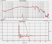
Below is an impulse measurement of a JBL 2227 band limited from 100-1200 Hz

Below is an impulse measurement of a JBL 2227 band limited from 100-1200 Hz
Take a closer look, with an eye on the scale of each graph - they are extremely close to the same. I think the only differences are due to the distance of the measurement taken. I'll post tomorrow to show that difference on the same scale, regardless, because I need to measure from farther away in order to get what I want for crossover design (both drivers measured from the same mic position - this is a 2-way attempt).The measurement you've shown in post 33 looks much more reflection free than your Arta measurement around the same gate length. The blue FR from post 33 looks right.
At this time of year, that's not very appealing, plus I live right in the city... I could try a groundplane.Can you measure outside? As a final check, you could do a groundplan measurement or something to get a raw response. Then what you get, is what it is...
1audiohack, yes, this is pretty much full bandwidth (30-100hz start, I haven't kept track of that very carefully). I'm not sure that either program I've been using allows for an upper limit to the sweep, but I'll check that out tomorrow.
Last edited:
I dunno. Looking at the 500 to 1000hz band on the Arta measurements is pretty wrinkly. Maybe I'm just more use to Holm...
Try to come up with an example described in dB and you'll see what I mean, I think. I'm looking at this on my phone at this point, so it's possible I'm putting my foot in my mouth.
edit: yep, I was. You're right about 500-1k looking different. That may be a gate taper difference. I'll have to check that out.
edit: yep, I was. You're right about 500-1k looking different. That may be a gate taper difference. I'll have to check that out.
Last edited:
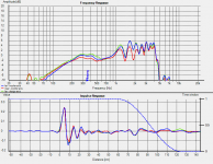
This may not be very useful for anything here, but I needed to see it, so here it is anyway. "Near" is around 15", "far" is 50". The design axis is 6" above the woofer center. I tried to match the impulse amplitude for the three.
P.S. The differences from ARTA mentioned above do appear to be from the gate taper - if I move the gate a little farther out, the small ripple in the 500-1k region does show up.
P.S. The differences from ARTA mentioned above do appear to be from the gate taper - if I move the gate a little farther out, the small ripple in the 500-1k region does show up.
Attachments
Last edited:
You know... going back to the real task hand (designing a speaker), what little of this bothersome behavior will make it through the crossover will, at the worst, affect the system response by +/- 1.5dB in the 1-2k range, and that's it. I should probably be more concerned about whether I'm getting an accurate picture of the average SPL between 500-2k, so that I end up with a flat midrange and get the HF driver padded correctly.
1. Normally, the ceiling or the floor is the first reflection surface how far away are these?
2. Near field measurement should be conducted only about an inch or so from these drivers of this size, do you have data that close?
3. I still think the spider might be the issue, it's necessary to look at unsmoothed impedance plots.
2. Near field measurement should be conducted only about an inch or so from these drivers of this size, do you have data that close?
3. I still think the spider might be the issue, it's necessary to look at unsmoothed impedance plots.
Floor is the closest, almost exactly 1m in the last measurement. I can get that to about 1.5m, and I think I will because I don't see that I have that saved right now, but I'm pretty sure you'll see the same thing.1. Normally, the ceiling or the floor is the first reflection surface how far away are these?
I did, but it looks like I didn't save it. Best as I can remember, it looked a lot like the measurements AE posted. I can do that easy though, wait a couple minutes.2. Near field measurement should be conducted only about an inch or so from these drivers of this size, do you have data that close?
What would I be looking for in that plot?3. I still think the spider might be the issue, it's necessary to look at unsmoothed impedance plots.
Look at the impulse of the impedance measurement, if it is there, then it most likely is the spider problem.
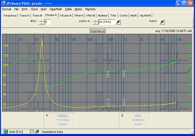
In the impedance plot, this would normally show up as a wriggle in the dip between F0 and the inductance impedance rise.
In the impedance plot, this would normally show up as a wriggle in the dip between F0 and the inductance impedance rise.
Look at the impulse of the impedance measurement, if it is there, then it most likely is the spider problem.
The spider "problem" might just be that the speaker is new, with stiff spider/surround, and just needs some time to get loosened up.
I have not seen these in person, but it from the data around the net, it seems the spider might be pretty large for a long throw, but not a progressive spider.
This is the mfg impedance measurement of the 8Ω version, if you guys haven't seen that:
I'm not sure when I'll be getting impedance measurements, as the Dayton WT3 has been out of stock for a while now, and I'm not sure if I want the Woofer Tester 2, which is the only affordable alternative that I'm aware of.
I'm not sure when I'll be getting impedance measurements, as the Dayton WT3 has been out of stock for a while now, and I'm not sure if I want the Woofer Tester 2, which is the only affordable alternative that I'm aware of.
Last edited:
This is the mfg impedance measurement of the 8Ω version, if you guys haven't seen that:
I'm not sure when I'll be getting impedance measurements, as the Dayton WT3 has been out of stock for a while now, and I'm not sure if I want the Woofer Tester 2, which is the only affordable alternative that I'm aware of.
WT-2 is the real deal, developed by Smith and Larson. WT-3 is...something different.
Well, I'm open to hearing a reason to choose one over the other. Being made by Smith and Larson, is not a reason, to me. PE sold the Smith and Larson device previously. I think I can sum up everything I've seen regarding the two with three types of comments:
1. Just get the WT3 - it's so much faster and easier
2. Just get the Woofer Tester 2 - the WT3 is cheap junk and mine [broke quickly or I couldn't get it to work on my computer or the results were inconsistent]. Then I got the Smith and Larson and everything was great.
2. Just get the WT3 - the Woofer Tester 2 is cheap junk and mine [broke quickly or I couldn't get it to work on my computer or the results were inconsistent]. Then I got the WT3 and everything was great.
P.S. Please try not to quote images unless there is a reason. It makes things very hard to read.
P.P.S. I just realized this post and the last come off as being anti-WT2. I'm not at all, and I may very well be about to buy one. It's just the Dayton unit is about 1/3 less $, and I'm not totally convinced the WT2 is superior.
Last edited:
Point taken, feel free to buy whatever you please. I'm sure either device will do a fine job.
P.S. Sorry about quoting the image. I'd go back and edit it out, but I can't seem to find any way to edit these posts.
P.S. Sorry about quoting the image. I'd go back and edit it out, but I can't seem to find any way to edit these posts.
Dumptruck, as you've used ARTA, load up LIMP instead. This is designed to take impedance measurements, the help file shows you what hardware you need for taking measurements, it's very minimal and pretty much fool proof and cant really go wrong either. Just don't overload the input to your sound card.
- Status
- Not open for further replies.
- Home
- Loudspeakers
- Multi-Way
- Has anyone here measured a TD15M? (I have them)