F5 dc
Hello
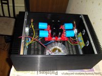
I am building av six channel F5, and are almost done with the setup. Five boards (Peter Daniel) channels measures fine - 0.60V along R11 and R12, and about 0Vdc on the output. But on the last board I get 24 Vdc on the output 😱 - it seems the rail voltage is just running through.
Any ideas what to look for, before I dismantle the board and start all over ?
Hello
I am building av six channel F5, and are almost done with the setup. Five boards (Peter Daniel) channels measures fine - 0.60V along R11 and R12, and about 0Vdc on the output. But on the last board I get 24 Vdc on the output 😱 - it seems the rail voltage is just running through.
Any ideas what to look for, before I dismantle the board and start all over ?
I assume you have not inserted components the wrong way.🙄Hello
I am building av six channel F5, and are almost done with the setup. Five boards (Peter Daniel) channels measures fine - 0.60V along R11 and R12, and about 0Vdc on the output. But on the last board I get 24 Vdc on the output 😱 - it seems the rail voltage is just running through. The feedback wont help then.
Any ideas what to look for, before I dismantle the board and start all over ?
This might mean an input jfet (2sk170) is short circuited; the drain resistor then bangs to the ground almost; the corresponding output FET is completely open.
or else . . .😱
you want serious , or less serious answer ?

 errr... ac-dc converter ...............? 🙂
Any ideas what to look for, before I dismantle the board and start all over ?
If i had that problem, i would start at the output, meassuring backwards through the circuit.
Easiest method, is if you had another channel fired up, to compare with... alternative you can compare with the two sides (Q3/Q5 ---> vs. Q4/Q6), but it would be a lot harder to figure it out that way...
Jesper.
You were right. The last board is now up and running.Check one of your 2sk170's
Thanks.
Someone did post the F5 turbo schematics but I cant find them.
The one on the STORE page is misleading as it's in Black and White and there seem to be connections where there shouldn't be.
I'm dubious about this - it's just the DIY bug has bitten again and I wonder if the F5T is any better than my very much loved Aleph 4.
Hi,
The F5Turbo schematics have not been published yet (someone was pranking).
The schematic at the DIYaudio store is the original one. Most people have built this version. The "R-1" release incorporates P3, value changes to some resistors and a rearranged protection circuit.
Tomorrow I'll listen some music to hear the difference.
I did and I should say that I prefer more distortion, not less. It seems to me that the sound become dryer when the thd is at the minimum. I went back (eliminating P3, thd ~10 times) and I liked the sound more. That's my feeling. Anyone else?
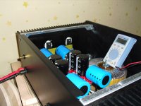
Very good amp Tolikas,
looks like you're thrown out protection circuit 😎.
your source resistors is not too hot? it seems that you have 2x 0.6W (in my f5 i have 5w resistors and there is approx. 60 degrees on them).
looks like you're thrown out protection circuit 😎.
your source resistors is not too hot? it seems that you have 2x 0.6W (in my f5 i have 5w resistors and there is approx. 60 degrees on them).
Protection circuit has a negative effect on overal l sound quality, i have tested it before throwing out...Very good amp Tolikas,
looks like you're thrown out protection circuit 😎.
your source resistors is not too hot? it seems that you have 2x 0.6W (in my f5 i have 5w resistors and there is approx. 60 degrees on them).
Those are 2x3w actually 🙂


 Me
Me 

Nope !
Have patience.
Just a few more night sleep and you'll be the first to see it 😀
Audiofanatic 😉
Have patience.
Just a few more night sleep and you'll be the first to see it 😀
Audiofanatic 😉
just finished my F5, outstanding performance.
I see you left room for F5 Turbo parts.
The text will be done in a few days - you will see it next week.
😎

The text will be done in a few days - you will see it next week.
That's what my wife keeps saying about her PhD thesis -- ever here the one about Penelope unweaving the shawl every evening?
That's what my wife keeps saying about her PhD thesis -- ever here the one about Penelope unweaving the shawl every evening?
who are the suitors then?
Hello,
I've not been able to find or to understand an explanation to the need of matching transistors in the original F5 amplifier.
Within a single channel, I "extrapolate" from various diyaudio threads that P and N MOSFETs don't need to be matched (also because they are technically different). But what about the JFETs?
I also "extrapolate" that matching MOSFETs and JFETs between left and right channel is not necessary (probably it's useful if I want to do the same operations to bias the two channels, but I'm not sure about it).
Any help is really appreciated 🙂
- Home
- Amplifiers
- Pass Labs
- F5 power amplifier