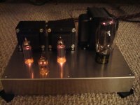
I've built my first tube amp with RH84 tube amp. It sounds good but I'm very surprised that it can actually sounded quite loud even with my 89dB/W/m speaker.
May I know why RH84 sounds better with cathode bypassed cap? i thought without bypass cap, the tube will be more linear because of degeneration. It sound restrain without bypass cap.
I connect two EL84 heater in series and power them with 12.6V AC supply. Is there any drawback with this series connection?
I connect two EL84 heater in series and power them with 12.6V AC supply. Is there any drawback with this series connection?
No.
Shoog
Brisso57 said:
To give me a starting point, can you provide the dimensions of your pictured amp?
After I get the amp built and working, I'll build the final housing/plinth.
Thanks
Doug
Doug-
A bit of background:
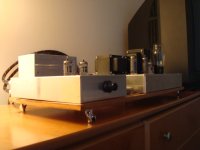
My RH84 is quite a bit bigger than it needs to be. When I built my Pointz 'MusicMachine', I made a spare chassis/enclosure, 'just in case' I made a mistake or wanted to build a 2nd one. I used it for the RH84, which I gave to my nephew as a Xmas present. (Great-sounding little amp, in spite of the very modest iron)
Notice that I used butt joints in my woodwork- easier to construct and the projecting 'ears' on the front help to protect the pot/switches if you have to pack or ship the amp. Miters would possibly look better.
The overlapping top plate (1/8" aluminum from the junkyard- cut with a non-ferrous metal blade on the tablesaw) and bottom covers are 'structural' and help to hold everything together. Total cost was under $10.
The open space between the power supply and amp sections in the Pointz enclosure makes the construction more complex. I'd recommend just keeping the same dimensions, but using a continuous top plate if you don't have a lot of tools.
Dimensions (in inches) are 21.5 x 10.5 x 3
I recommend building the enclosure first, before mounting and wiring components. It's a known design which will work, so no breadboarding is necessary. Also, you don't want exposed 400v wiring around the house.
Cheers
John
Under chassis view
Howdy,
Nice work on the amp chassis posted recently. Would you happen to have a picture from underneath? Would like to see how you guys did the wire routing.
Thx,
Howdy,
Nice work on the amp chassis posted recently. Would you happen to have a picture from underneath? Would like to see how you guys did the wire routing.
Thx,
layout
here ya go.
i dont know how but it wont let me post the pics
but i have posted them on photo galery
here ya go.
i dont know how but it wont let me post the pics
but i have posted them on photo galery
Tim,
Very nicely done! I'll use that for inspiration. Tell me is that cat5 twisted pair you are using for the heaters?
Very nicely done! I'll use that for inspiration. Tell me is that cat5 twisted pair you are using for the heaters?
Thanks CUBBY!
yes it cat5 from the cable man, had it laying around might as well
make use of it 😀
yes it cat5 from the cable man, had it laying around might as well
make use of it 😀
Re: did some one said RH84?
Well done. Same chassis (actually mine are a size down) that our RH84 stereo and mono-bloks are on.
dave
tim614 said:here's mine aluminium (hammond $20) 12x8. i like to keep it as simple as i can you dont save much on diy chassis if cost was an issue.
Well done. Same chassis (actually mine are a size down) that our RH84 stereo and mono-bloks are on.
dave
the pre?
And what pre would that be, if I may ask? Maybe by the same author, the line section of the RPA... or maybe not.
What is the criteria you apply in choosing your pre? Frankly, while I am not a passive pre advocate, you do not need much gain with the RH84...
Regards,
Alex
i also just finish a pre (mate) for the RH84.
And what pre would that be, if I may ask? Maybe by the same author, the line section of the RPA... or maybe not.
What is the criteria you apply in choosing your pre? Frankly, while I am not a passive pre advocate, you do not need much gain with the RH84...
Regards,
Alex
Re: the pre?
The pre is the bottlehead i got from a friend it was not working properly, so as a newbie i like to fix things, so i rebuilt it from the ground up. i figure they looks good together😀
BTW; Alex, for my next build i would love to try your 300b design but some how i cant E-mail you on ur site.
So if i may can you send me a copy?
My e-mail
luanph03@yahoo.com
thanks
Tim
Hi Alex.Alex Kitic said:
And what pre would that be, if I may ask? Maybe by the same author, the line section of the RPA... or maybe not.
What is the criteria you apply in choosing your pre? Frankly, while I am not a passive pre advocate, you do not need much gain with the RH84...
Regards,
Alex
The pre is the bottlehead i got from a friend it was not working properly, so as a newbie i like to fix things, so i rebuilt it from the ground up. i figure they looks good together😀
BTW; Alex, for my next build i would love to try your 300b design but some how i cant E-mail you on ur site.
So if i may can you send me a copy?
My e-mail
luanph03@yahoo.com
thanks
Tim
Hi!
If you were to use it without pre-amplifier how would you change the input then?
Will you keep the 220R resistor?
What potentiometer to use?
Perhaps also an input switch?
Woul you mind clarifying this for me?
Best regards
Martin
If you were to use it without pre-amplifier how would you change the input then?
Will you keep the 220R resistor?
What potentiometer to use?
Perhaps also an input switch?
Woul you mind clarifying this for me?
Best regards
Martin
RH84 without pre
If one was to use the RH84 without an active preamplifier, the best solution would be to build it as an integrated amp. That would keep the wiring short and everything tidy as possible.
Basically, you have to add a selector, the appropriate number of RCA/cinch connectors, and a pot.
The pot should most probably be a 100k log, eventually a 47k log. I presume that most people conceive passive preamps around a 100k or even 220k pot.
I believe your question is about the 220r resistor in series with the grid of the input tube?
To cut a long story short, I WOULD KEEP EVERYTHING AS IT IS and just add the pot in front of the schematic as known... of course, the selector should be added in front of the pot 🙂
To repeat myself, the 220r or whichever similar value in series with the input tube is a grid stopper and is necessary as far as I am concerned. The grid resistor (some call it bleeder) between the grid and ground is also necessary, regardless of the presence of the pot. That because the pot could eventually fail, and you would be left without ground reference for your input tube's grid.
Some would find a lot to criticise to the above aproach, but frankly, grid stoppers and grid resistors (bleeders) are just a mark of good design and of thinking in advance.
It should be noted, though, that I do not advocate passive preamps, and try to make my amps less sensitive than one would expect, thus forcing the use of an active pre. Of course, as with the choice of tube types, which have to fulfill a task not satisfy a need for sonic virtues, that is not always possible 🙂
Regards,
Alex
Both of our RH84 have a 100k pot on the front instead of the grid resistor. No selector so each is a single input integrated. We did this to faciliatate bi-amping, althou in the end they usually get used at full wick.
Really nice to be able to pull the stereo one out on the garage apron, plug the iPod in (w full rex tunes), the big OBs and have a listening session outside.
dave
Really nice to be able to pull the stereo one out on the garage apron, plug the iPod in (w full rex tunes), the big OBs and have a listening session outside.
dave
Both of our RH84 have a 100k pot on the front instead of the grid resistor.
Ha, ha! You do that on your own and after this confession, I have nothing to add. You have just invalidated your warranty 😉
For the record, I feel more comfortable with the grid resistor in place.
Alex, et al:
I built the RH84 style amps that Dave referred to in post #115, and was quite impressed with the overall performance. He may have neglected to mention they were a bit of a collection of ideas, including trioded EF86 for driver, and parafeed connection on the output. They've been in more or less constant service for at least 5 years with no issues to speak of, so you're off the hook warranty-wise. 😉
My real question for yourself or other is regarding application of this style of feedback to Push Pull output stage (most likely candidate at the moment is a soon to be re-purposed Jolida SJ302 EL34)
I'm primarily a speaker cabinet guy, so the math and theory are beyond my grasp, but I have no trouble following a schematic and parts list.
Any observations or advice would be gratefully appreciated.
Last edited:
There are many different PP amps with Partial feedback.
I have built an ECL82 headphone PP amp which should come up with a search of the forum.
I have also built a version of the 807 based Tabor amp which should be searchable. Gary Pimms website has a few versions of the original TABOR.
I recently built a self splitting PL86 amp using partial feedback, searchable again.
Probably the best implementation out there is the BABY HUEY which has an extensive thread.
So plenty to chew over.
Shoog
, including trioded EF86 for driver, and parafeed connection on the output. They've been in more or less constant service for at least 5 years with no issues to speak of, so you're off the hook warranty-wise.
My real question for yourself or other is regarding application of this style of feedback to Push Pull output stage (most likely candidate at the moment is a soon to be re-purposed Jolida SJ302 EL34)
Hey,
Remember a partial/inverse feedbacked tube has a Zin of 2-4kohm dependant of load and Gm. This means the driver has to be capable of delivering lots of current. Do the math to estimate how much is needed.
salvaged mono-block variation
Hi,
I'm pretty new around here, but I've been doing a lot of reading. It's a fantastic community.
I am about to order parts for a mono-block pair of RH84s. The iron is coming from Akai M-5 amps. So far I'm unsure about two things:
1. I read somewhere that Planet10 used an EF86 per side on one of his builds. For mono-blocks, this seems a more elegant solution than using half of an ECC81. Do any component values nee to be adjusted to accommodate this change? Is this the most logical solution for a mono-block build?
2. The M-5's power transformer secondaries don't quite match what's called for in the schematic:
M5= 250V, 0, 250V, 6.3V 1.8A, 6.3 0.6A, 5.7V 0.3A
RH84= 300V, 0, 300V, 6.3, 6.3, 5V 3A
From what I've read, this will work but the power of the amp will be slightly reduced. But again, do any component values need to be adjusted to run it on 250V? Which of the smaller secondaries should be used for the rectifier anode?
thanks!
- Status
- Not open for further replies.
- Home
- Amplifiers
- Tubes / Valves
- Building RH84 SE tube amp.