could you be more spesific on what pin i've to measure?
thanks
All pins ref to gnd (psu and input gnd)
ok, i'll do it asapAll pins ref to gnd (psu and input gnd)
Mr. Mile
this is what i've measured on NE5532 pins
PSU GND to pin:
1. 61mV
2. 1.4mV
3. 0mV
4. -15.64V
5. 0mV
6. -0.8mV
7. -63.5mV
8. 15.68V
Input GND to pin:
1. 61.6mV
2. 1.5mV
3. 0mV
4. -15.65mV
5. 0mV
6. -0.8mV
7. -62.6 mV
8. 15.67V
thanks
this is what i've measured on NE5532 pins
PSU GND to pin:
1. 61mV
2. 1.4mV
3. 0mV
4. -15.64V
5. 0mV
6. -0.8mV
7. -63.5mV
8. 15.68V
Input GND to pin:
1. 61.6mV
2. 1.5mV
3. 0mV
4. -15.65mV
5. 0mV
6. -0.8mV
7. -62.6 mV
8. 15.67V
thanks
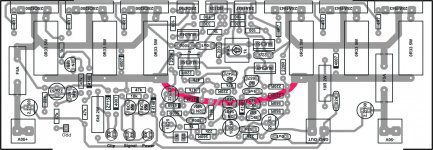
AX-20 with 3 pair of final tr...with led indicator and zobel network on pcb...
What is max voltage??and how about power dissipation at 4 or 8 ohm??
Regards
hi qq12,
which software ur using to design this pcb?
Mr. Mile,
may i use tl072 instead of lf353?
thanks
Use TL072 or better use LF412 if it's available.
Regards
AX-20 with 3 pair of final tr...with led indicator and zobel network on pcb...
What is max voltage??and how about power dissipation at 4 or 8 ohm??
Regards
For 3 pair of final use 2x50vac 500VA transformer (1000VA for stereo)
Regards
Mr. Mile
this is what i've measured on NE5532 pins
PSU GND to pin:
1. 61mV
2. 1.4mV
3. 0mV
4. -15.64V
5. 0mV
6. -0.8mV
7. -63.5mV
8. 15.68V
Input GND to pin:
1. 61.6mV
2. 1.5mV
3. 0mV
4. -15.65mV
5. 0mV
6. -0.8mV
7. -62.6 mV
8. 15.67V
thanks
Mr. Mile, is this measurement result is ok?
Mr. Mile
this is what i've measured on NE5532 pins
PSU GND to pin:
1. 61mV
2. 1.4mV
3. 0mV
4. -15.64V
5. 0mV
6. -0.8mV
7. -63.5mV
8. 15.68V
Input GND to pin:
1. 61.6mV
2. 1.5mV
3. 0mV
4. -15.65mV
5. 0mV
6. -0.8mV
7. -62.6 mV
8. 15.67V
thanks
1,5mV on inverted input (pin 2) and 61,6mV on inverter output (pin 1) is wrong. Output (pin 7) of second inverter is ok -62,6mV for 61,6mV input from first inverter output (pin 1).
thanks Mr. Mile. what it's should be value for pin 1 and pin 2?1,5mV on inverted input (pin 2) and 61,6mV on inverter output (pin 1) is wrong. Output (pin 7) of second inverter is ok -62,6mV for 61,6mV input from first inverter output (pin 1).
For 3 pair of final use 2x50vac 500VA transformer (1000VA for stereo)
Regards
Does my design correct????
Regards
thanks Mr. Mile. what it's should be value for pin 1 and pin 2?
Value isn't mater, but must be invert polatity on output.
AX-20 with 3 pair of final tr...with led indicator and zobel network on pcb...
What is max voltage??and how about power dissipation at 4 or 8 ohm??
Regards
Hi QQ12e5k1,
Do you have bottom layout of your pcb? Can you share it?
Regards.
thanks, i got the point.Value isn't mater, but must be invert polatity on output.
i 'm waiting for lf412 and lf353, hope my dc servo will work.
regards
Last edited:
Sorry for my stupid question
thanks for this link...
i just beginner diy,
i hope understand, for my stupid question
i read this thread until page 211,and there is no size pcb given,
Post 1039You have PCB for thermo-transfer (toner), size - 60x82,5mm
thanks for this link...
i just beginner diy,
i hope understand, for my stupid question
i read this thread until page 211,and there is no size pcb given,
- Home
- Amplifiers
- Solid State
- 100W Ultimate Fidelity Amplifier