Very nice George, congrats
Just a question: where did you connect SSHV2 sense + and -?
Sense + to the #26 anode and sense - to the star gnd?
Just a question: where did you connect SSHV2 sense + and -?
Sense + to the #26 anode and sense - to the star gnd?
Maybe 170Vdc. Pls, either simulate or make a test. There is going to be some voltage sag.
I like to have higher voltage transformer and adjust B+ with a small capacitor in front of the choke.
I like to have higher voltage transformer and adjust B+ with a small capacitor in front of the choke.
Very nice George, congrats
Just a question: where did you connect SSHV2 sense + and -?
Sense + to the #26 anode and sense - to the star gnd?
Correct, but as I use a transformer, sense and force + to it' s input, not to anode.
Thank you. I asked this question because I saw a red wire coming out from the SSHV2 going apparently to the tube anode. I was wrong then.Correct, but as I use a transformer, sense and force + to it' s input, not to anode.
It's one red wire coming from the transformer. Two red wires leaving SSHV2 going to transformer.
I think there's a growing bunch of people who see filament bias as the best sound you can get out of the 26. I know most of you don't start with a small cap (220uF) and choke input before the filament reg, but I found this gave a nice increase in sound quality. I use 280mH chokes rated at 2.7A - simply because I bought a few off a dealer. But Hammond chokes are another option.
We seem to be moving towards a "standard" design with filament bias and a Salas reg. LL1660 seems to be the default transformer option, but I'm sure there are some tasty hand made options out there as well, and there are some very skilled winders on this forum.
andy
We seem to be moving towards a "standard" design with filament bias and a Salas reg. LL1660 seems to be the default transformer option, but I'm sure there are some tasty hand made options out there as well, and there are some very skilled winders on this forum.
andy
Wich dimensions have your chassis?
43X33cm PS unit 43X26
filament board brought almost 6 months ago
Hi Rod,
I still have a pair of your boards sitting on the bench of which brought out from you almost 6 months ago. I'm going to cut my chassis and lately found that people have good result on filament bias. Are my boards suitable for the purpose by changing some value of parts ?? Please kindly advise.
Regards
Albert
Hi George, Looks like good layout and build!
Voltage Rating for Filament Bias:
With correctly specified C1 and R8, any new kit can be configured to run Filament bias up to 45V or so at the input.
With changes of transistor 200V is possible - though I can't imagine it is needed.
Flexible operating voltage - the beauty of discrete-transistor design! New V4 kits are available for Filament bias.
Hi Rod,
I still have a pair of your boards sitting on the bench of which brought out from you almost 6 months ago. I'm going to cut my chassis and lately found that people have good result on filament bias. Are my boards suitable for the purpose by changing some value of parts ?? Please kindly advise.
Regards
Albert
Thanks Massimo!
This is still valid, so I can paste it in here:
Filament Bias is possible with all versions of the 26 Filament Regulator.
Here's what to do, if you use the 10-Ohm Resistor, as published by Andy:
The Raw dc voltage should be about 16,5V .. 18V. The Filament current is 1,05A - and gives about 12V at the output of the regulator, when adjusted correctly.
2x 10000uF/35v; 1N5822 rectifiers. resistors adjusted to give 16,5V to 18V at the regulator input terminals. See the PDF App Notes, for building a raw dc supply.
The Regulators are modded:
C1= 47uF/35V Panasonic AM (From Farnell. this has been tested.... Nichicon VR should be OK too, from Mouser)
R8 change to 470 (if you have 220 there now); or change to 1,8K (if you have 1K there now).
The down side to filament bias is a big increase in rectifier pulse current. The trafo/rectifier/caps must be wired with VERY short leads to prevent magnetic coupling from these pulses into your amp. Put them in a shielded box, away from the tubes!
Alternatively, find a big choke 3.3-22mH or more (at 2A) and use PSUD2 to work out a choke-input supply. This also should be kept away from the tubes, but potentially offers the ultimate in performance.
After several hours of reading yesterday morning I was still as confused as when I started reading the thread. I saved and copied several schematics and then went to the garage in a mad search for parts. Well, I have some Hammond 157 chokes 40mA and several 156's at 8mA I believe for plate chokes. Transformers yup have them too. Thinking along the lines of a dual mono block #26 line stage. A waste of parts ...well maybe but then again the 26 from what I read is a complex little humming bastard. Power transformers yup two of them off ebay massive but very little money in them. I have two big 9-0-9 10A transformers also for the filament supply.
So..... Grid bias or filament bias? Some here say filament and some say grid. Naturally the expensive power transformers will deliver superior performance but at a price. The output transformer has got to be spot on in performance as well as a nice input control.
The question is... with the run of the mill parts I have on hand I still need a constant current source to lower the ripple and improve performance of the B+ supply. So, which one and how much? Then I need some type of filament regulated power supply so again who do I buy it from and how much?
CCS ahead of a shunt regulator? Looking at Coolzero's power supply schematic and 3.3K resistor ahead of the 200H plate choke for better low frequency response or after the choke?
For B+ regulation, SSHV (now in version 2) http://www.diyaudio.com/forums/power-supplies/134801-simplistic-mosfet-hv-shunt-regs-207.html, is a good choice. Version 1 was build by many with positive results.
I would not put a resistor between regulator, choke and anode.
You can also have a look at battery bias.
For filament supply, ask Rod Coleman.
I would not put a resistor between regulator, choke and anode.
You can also have a look at battery bias.
For filament supply, ask Rod Coleman.
🙂 for lazy people like me just use a 2X 12V transformer with two low noise 1amp Tenlab filament bias regulator and you will get great sounds without hum or noise..
lundahl CCS as B+ regulation ... lazy you say ?
lundahl CCS as B+ regulation ... lazy you say ?
Last edited:
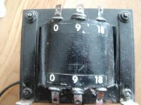
I have two big 9-0-9 10A transformers also for the filament supply.
So..... Grid bias or filament bias? Some here say filament and some say grid. Naturally the expensive power transformers will deliver superior performance but at a price. The output transformer has got to be spot on in performance as well as a nice input control.
If you have 9-0-9V 10A trafos, then you can make the perfect raw dc for Filament Bias, with only a very modest cost.
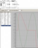
The attached PSUD2 grab shows the 9-0-9 series connected, feeding a quasi-choke-input supply. The Choke is a Hammond 159ZE or similar (28mH, 430mR dc, 3A rated. The 15000uF C2 only sees a ripple of 300mA rms, so any variety should work perfectly under such low stress. C1 should be Panasonic FC or similar quality high ripple handling: 2x 220uF 35V.
The quasi-choke-input configuration means lower impulse current through the trafo-rectifier- and this supply will deliver 17 -18Vdc: perfect raw dc for Filament Bias using my regulator kits. They are self assembly kits, so the price is low. You can click my name to send some email - I have PDF manuals and App Notes on getting best sound through better filament heating.
Attachments
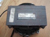
Looked up the specs on the transformer 36vct @ 8A in series or 18vct@ 16A in parallel. Will this work ok?
Attachments
Last edited:
Albert, while you wait for Rod's reply, see post #1328 😉
Happy new year to everybody!
Massimo,
Thanks and Happy 2012
Albert
Thanks Massimo!
This is still valid, so I can paste it in here:
Filament Bias is possible with all versions of the 26 Filament Regulator.
Here's what to do, if you use the 10-Ohm Resistor, as published by Andy:
The Raw dc voltage should be about 16,5V .. 18V. The Filament current is 1,05A - and gives about 12V at the output of the regulator, when adjusted correctly.
2x 10000uF/35v; 1N5822 rectifiers. resistors adjusted to give 16,5V to 18V at the regulator input terminals. See the PDF App Notes, for building a raw dc supply.
The Regulators are modded:
C1= 47uF/35V Panasonic AM (From Farnell. this has been tested.... Nichicon VR should be OK too, from Mouser)
R8 change to 470 (if you have 220 there now); or change to 1,8K (if you have 1K there now).
The down side to filament bias is a big increase in rectifier pulse current. The trafo/rectifier/caps must be wired with VERY short leads to prevent magnetic coupling from these pulses into your amp. Put them in a shielded box, away from the tubes!
Alternatively, find a big choke 3.3-22mH or more (at 2A) and use PSUD2 to work out a choke-input supply. This also should be kept away from the tubes, but potentially offers the ultimate in performance.
Rod,
Big thanks and happy 2012
I might not have the 1N5822, but have some fast recovery type 60v 8A
Albert
Looked up the specs on the transformer 36vct @ 8A in series or 18vct@ 16A in parallel. Will this work ok?
As 18V CT, it will be perfect for the PSUD2 example, shown above. If the dc voltage comes up above 18V under load, just reduce C1 a touch (eg 220uF + 100uF parallel).
- Home
- Amplifiers
- Tubes / Valves
- #26 pre amp