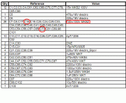
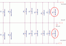
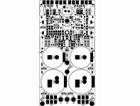
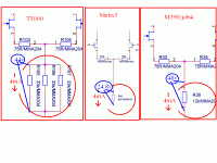
C18,C73 not found on the circuit diagram but it have in the part list,it might be option😕
C18,C73: 100nF/100V MKS2 Wima
C18,C73: 100nF/100V MKS2 Wima
Attachments
Last edited:
Is C65, and C24 missing also?
Well,sorry
C65,C73 is bypass capacitor for Vcc(power)
I am not found C18,C24 on schematic Metis3
Attachments
The new vesion
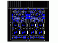
The new vesion of the clone Goldmund Amplifier,today I re-layout with dual channel versions.
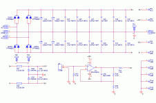
Original metis 3 circuit(#390.2)
All in one,dual chanel,very compact, using SMD components, ... compatible with heatsink have the length > 16cm(heasink in picture my layout is 19cm)
Appropriate for many types of chassis.
Happy New Year
Regards.
Attachments
Last edited:
Very appealing PCB, it's just that I don't like this kind of output BJT assembly, it is self limiting and has good thermal spreading only in installation you've suggested. PSU part has only 3200uF per rail, this is not nearly sufficient for two pairs of outputs per channel. 32000uF sounds more adequate ... 🙄
thank for your comments.Very appealing PCB, it's just that I don't like this kind of output BJT assembly, it is self limiting and has good thermal spreading only in installation you've suggested. PSU part has only 3200uF per rail, this is not nearly sufficient for two pairs of outputs per channel. 32000uF sounds more adequate ... 🙄
Hix,this is the original circuit😀
I've said in the topic"The Very Best Amplifier I Have Ever Heard!!!! "
Have two ways to have great sound with Goldmund circuit(lateral mosfet output) is:
1. High current bias(200-300mA), with power supply enough clean (large capacitance>10.000uF or parallel multiple small capacitors),it raises more heat,heatsink must be large enough.Goldmund does not choose.
2. Low current bias(70-90mA), the power supply does not need too clean(for Power Amplifier stage - Output).Goldmund has chosen this option,so they just choose capacitors for the power supply is 2200uF +1000uF = 3300uF.Their heatsink is very small.
Because the small capacitance means is the impedance power supply will be greater,it raises many harmonic distortion on the load speakers, when considering the load resistor to announce the results, it is very low harmonic distortion but the reality is not so, the speaker is not the same as resistance.
Sounds great,to less expensive materials,structure machine not bulky,be durable by very low-temperature,little damage, very aesthetic,...
Regards.
Last edited:
OK, maybe appropriate SMPS would do much better than this but anyway I like the channel schematic, especially double input fet. 😎
One day I'll do the amp involving this one or LS5912 from Linear Systems. 😉
P.S. BTW 2200+1000=3200 😀
One day I'll do the amp involving this one or LS5912 from Linear Systems. 😉
P.S. BTW 2200+1000=3200 😀
Last edited:
Nice work. R25?, R2?, Not MM390.2
My opinion is the value of resistance has not influence to the quality of the amplifier.
Because impedance of ccs is very large,if connected with an resistor is also not different.
The main task of this resistor is reduce Vce NPN(made ccs) also is reduce temperature for this BJT.
I do not understand why Goldmund changed value this resistor in their circuits,
Although in theory it only should ensure that Vr = Rx4mA < 50V => R< 12.5k is ok.
Regards,
Some original circuit:
Attachments
Last edited:
The new vesion of the clone Goldmund Amplifier,today I re-layout with dual channel versions.
Original metis 3 circuit(#390.2)
All in one,dual chanel,very compact, using SMD components, ... compatible with heatsink have the length > 16cm(heasink in picture my layout is 19cm)
Appropriate for many types of chassis.
Happy New Year
Regards.
Hi
I'm very interested in your project , this is ver ULC , and i like it 🙂
Can I register a set of Board .
🙂
always support you
Happy New Year .
The previous versions, I only used to make the complete my amplifier
This is the cheap version that I will share PCB to all those interested 😀
Everybody can register in the list order PCB.
I will provide for all.😀
Regrads,
This is the cheap version that I will share PCB to all those interested 😀
Everybody can register in the list order PCB.
I will provide for all.😀
Regrads,
Last edited:
Hi
Arcording to some friends at VNAV Portal - Trang ch? forum you and the OP live very close to each other , so just come and pick up board why have to create list..
Regards
Arcording to some friends at VNAV Portal - Trang ch? forum you and the OP live very close to each other , so just come and pick up board why have to create list..
Regards
Last edited:
Functions protection of the Metis3 is:Analogue output protection? On a separate board?
-Turn on relay slower a few seconds when power on
-Turn off relay fast when power off
-Turn off relay when B+ reduce.
Not protect DC on the output amplifier,not protect when over current,...
So I remove it to direct output to speakers😕
Regrads,
Last edited:
- Status
- Not open for further replies.
- Home
- Amplifiers
- Solid State
- Clone Goldmund Amplifier
