Hi everyone and Merry Christmas.
Apex I have a question, I can replace 2N5401 to BC556B. Putting it in reverse? And BD139 to BD137? Trafo has 2x35VAC
Apex I have a question, I can replace 2N5401 to BC556B. Putting it in reverse? And BD139 to BD137? Trafo has 2x35VAC
Hi everyone and Merry Christmas.
Apex I have a question, I can replace 2N5401 to BC556B. Putting it in reverse? And BD139 to BD137? Trafo has 2x35VAC
Yes, it's OK
how to set bias and dc offset?
hi Mr. Mile
i've build your AX17S, it work nice...sound is comparable with my GC even i only use standar componet. This is my first Solide State i've ever build.
I use +-44 volt DC.
there are few question i want to ask:
1. how to set bias? i've measured 0R33 and can't get fix value, is this normal?
2. my dc offset is about 34mv is this normal too?
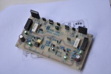
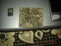
attach is pic of AX17S build
thanks and regards
naf
hi Mr. Mile
i've build your AX17S, it work nice...sound is comparable with my GC even i only use standar componet. This is my first Solide State i've ever build.
I use +-44 volt DC.
there are few question i want to ask:
1. how to set bias? i've measured 0R33 and can't get fix value, is this normal?
2. my dc offset is about 34mv is this normal too?
attach is pic of AX17S build
thanks and regards
naf
Attachments
Set 15mV across 0,33R for 50mA bias. PN voltage is 550mV like zener voltage, and you can't set bias with measure Vbe multiplayer voltage, and for TEF it's will be about 3,2V for any bias current. With 2,4V on Vbe multiplayer amp work in class B.
Regards
Dear Mr. Mile,
i measured voltage across 0,33R without load i get 0mV, and with load i get about 3-15mv up and down.
"...and for TEF it's will be about 3,2V for any bias current"... how to measured this?
thanks and regards
naf
Dear Mr. Mile,
i measured voltage across 0,33R without load i get 0mV, and with load i get about 3-15mv up and down.
"...and for TEF it's will be about 3,2V for any bias current"... how to measured this?
thanks and regards
naf
Replace R21 (1k) with 1,2k or 1,5k and you can set 15mV across 0,33R.
Offset must be 1mV with DC servo. You can test amp without DC servo just remove R36 (1k) and add 220uF in series with R15 (22R),
Regards
Many thanks Mr. Mile, i'll try your suggestion and post the result.Replace R21 (1k) with 1,2k or 1,5k and you can set 15mV across 0,33R.
Offset must be 1mV with DC servo. You can test amp without DC servo just remove R36 (1k) and add 220uF in series with R15 (22R),
Regards
regards
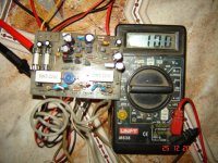
Gentlemen, I have a problem. 14.38 VDC output and do not know what is. I repalece BC547 - BC546B, BC557 - BC556B, 2N5401 - BC556B reverse, BD139 - MJE340. Instead 0,33R i put 0,22R. P1 set 10mV on 0,22R, all transistors tested and look good, any idea what is wrong?
Gentlemen, I have a problem. 14.38 VDC output and do not know what is. I repalece BC547 - BC546B, BC557 - BC556B, 2N5401 - BC556B reverse, BD139 - MJE340. Instead 0,33R i put 0,22R. P1 set 10mV on 0,22R, all transistors tested and look good, any idea what is wrong?
You must connect input gnd to psu gnd for test, many people made same mistake.
Can you post pictures?
Regards
Last edited:
AX-14
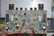
Haha thanks Apex, now work 🙂 i must remember for the future... Bias is 10mV . DC output is ~ 1mV. I have a little weak trafo, only 2x45VDC and drops to 2x40VDC under load. Next be made HV350, and I think it enough for me😉 AX14 will be to the subwoofer, work with HL2. I'm interested in class "H" I've never heard of such an amplifier.
Anyway, thanks for the diagrams... And i'm thinks AX14 is good for home audio for normal people hehe.
Attachments

I was one of them,with NX14. Same mistake with both channel. DC offset was 30VDC,gone with connecting input ground with PSU ground,just as APEX said.You must connect input gnd to psu gnd for test, many people made same mistake.
Can you post pictures?
Regards
I missed that in wireing amp... 😀
Haha thanks Apex, now work 🙂 i must remember for the future... Bias is 10mV . DC output is ~ 1mV. I have a little weak trafo, only 2x45VDC and drops to 2x40VDC under load. Next be made HV350, and I think it enough for me😉 AX14 will be to the subwoofer, work with HL2. I'm interested in class "H" I've never heard of such an amplifier.
Anyway, thanks for the diagrams... And i'm thinks AX14 is good for home audio for normal people hehe.
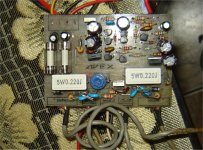
Nice work, but put outputs and drivers on pcb without wires.
Regards
Yes of course 😉 Wires is only for test, i have heat from other amp whit pair 2SC5200/ 2SA1943 and I want to see who plays better. I think it's your have a more bass 😀 , good dynamic, maybe louder sound 😕 later I'll add him another pair "AX20", pity that there is a silent shutdown integrated on PCB, on some transistors...Nice work, but put outputs and drivers on pcb without wires.
Regards
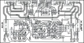
P.s. You have maybe PCB Layout for AX20 ??
Mr. Mile,
thanks for your suggestion, (i use 1k +330R in series) now i can turn my 1k Pot to adjust bias on 0.33R... and it's very difficult to set even i use multiturn pot, when i close to 15mV value suddenly it jump to 200mv. Any suggestion?
and for DC offset of my AX17S, i've done all your suggestions and my DC offset down to 15mV (without dc servo). What your next suggestion to correct my dc servo circuit?
thanks and regards
naf
Mr. Mile,
thanks for your suggestion, (i use 1k +330R in series) now i can turn my 1k Pot to adjust bias on 0.33R... and it's very difficult to set even i use multiturn pot, when i close to 15mV value suddenly it jump to 200mv. Any suggestion?
and for DC offset of my AX17S, i've done all your suggestions and my DC offset down to 15mV (without dc servo). What your next suggestion to correct my dc servo circuit?
thanks and regards
naf
Add zobel network on amp out 100nF+10R, and try set bias. With HF instability you get bias and offset instability.
I have got pcb for this amplifier today. And after new year, i will finish this amps... so i will be one more proud owner of D14 amp.
Tnx Apex!
Tnx Apex!
thanks for your suggestion Mr. Mile. I'll try it and post the result ASAPAdd zobel network on amp out 100nF+10R, and try set bias. With HF instability you get bias and offset instability.
Hi everyone I've been following this thread for a while and begining to build the AX14.
I have a 54-0-54 6A transformer. I'm guessing it should work for the design, but if anyone could help I would apreciate it. Thx everyone specially Mile
I have a 54-0-54 6A transformer. I'm guessing it should work for the design, but if anyone could help I would apreciate it. Thx everyone specially Mile
Hi everyone I've been following this thread for a while and begining to build the AX14.
I have a 54-0-54 6A transformer. I'm guessing it should work for the design, but if anyone could help I would apreciate it. Thx everyone specially Mile
Use regulated PSU5 ans set +/-55V DC output voltage, without regulated psu this transformer can't be use for AX14, ac voltage is to high.
Regards
- Home
- Amplifiers
- Solid State
- 100W Ultimate Fidelity Amplifier