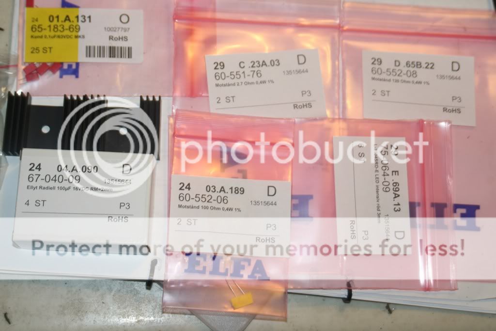
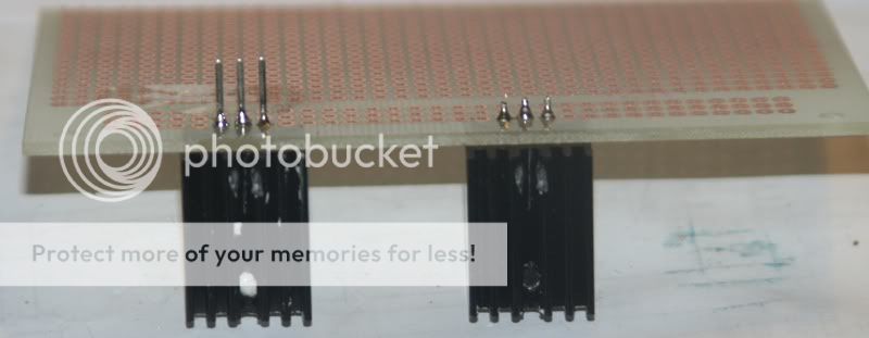
I've gotten all the parts for the TPR.
If the heatsinks are too small(bigger then the other ones previously shown though) could I just use 2 per LM317T? Back to back so to speak.
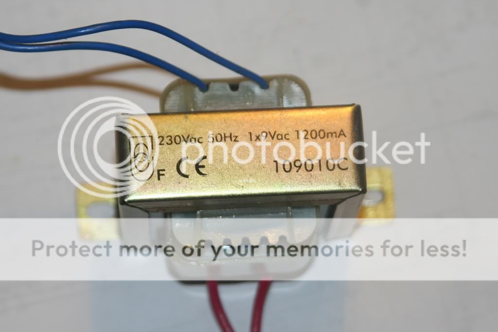
Either I use this transformer, or I "steal" supply DC from some where on the main PCB. Don't know which option is the better one.
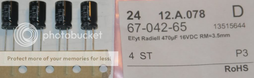
Also recieved 4pcs of Rubycon ZLH 471uF/16V. What's my best approach? Putting them parallel to the elcos after the regs or replacing elcos after regs completely with these?
If the heatsinks are too small(bigger then the other ones previously shown though) could I just use 2 per LM317T? Back to back so to speak.
Either I use this transformer, or I "steal" supply DC from some where on the main PCB. Don't know which option is the better one.
Also recieved 4pcs of Rubycon ZLH 471uF/16V. What's my best approach? Putting them parallel to the elcos after the regs or replacing elcos after regs completely with these?
Heatsinks look fine! You'll only need them on the 7220 and poss 7210 in any case. Most of the transformers I are bigger than that ;-)
Are you getting more caps? Those rubycons are only 40p each in the UK!!!
Are you getting more caps? Those rubycons are only 40p each in the UK!!!
Heatsinks look fine! You'll only need them on the 7220 and poss 7210 in any case. Most of the transformers I are bigger than that ;-)
Are you getting more caps? Those rubycons are only 40p each in the UK!!!
I paid 5,15 SEK each, that's roughly 50p.
So not that bad, they do have a limited range of values in that online store though.
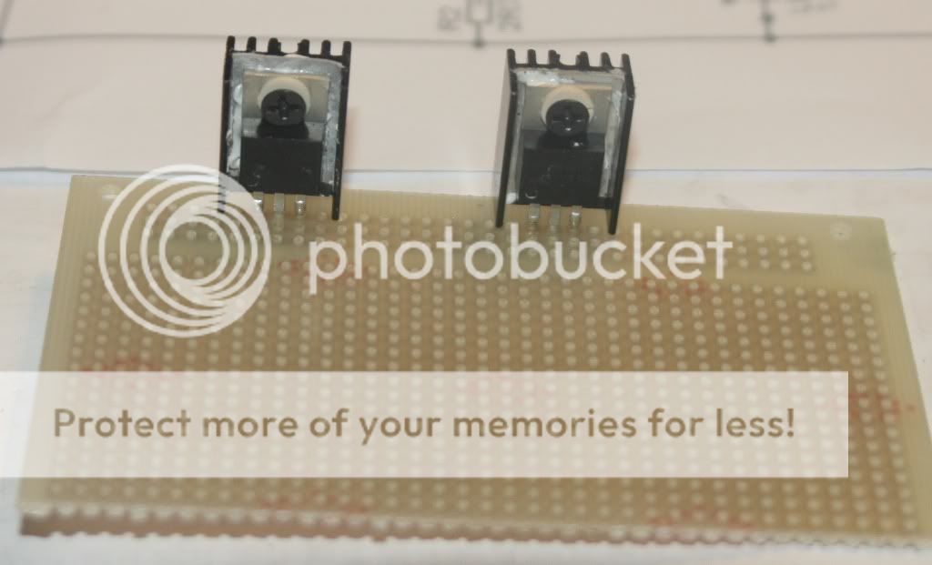
Started on the TPR, left enough space between LM317's to fit bigger heatsinks.
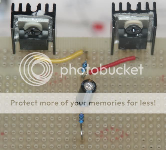
Might not be pretty, but there's connection where it should be and no shorts.
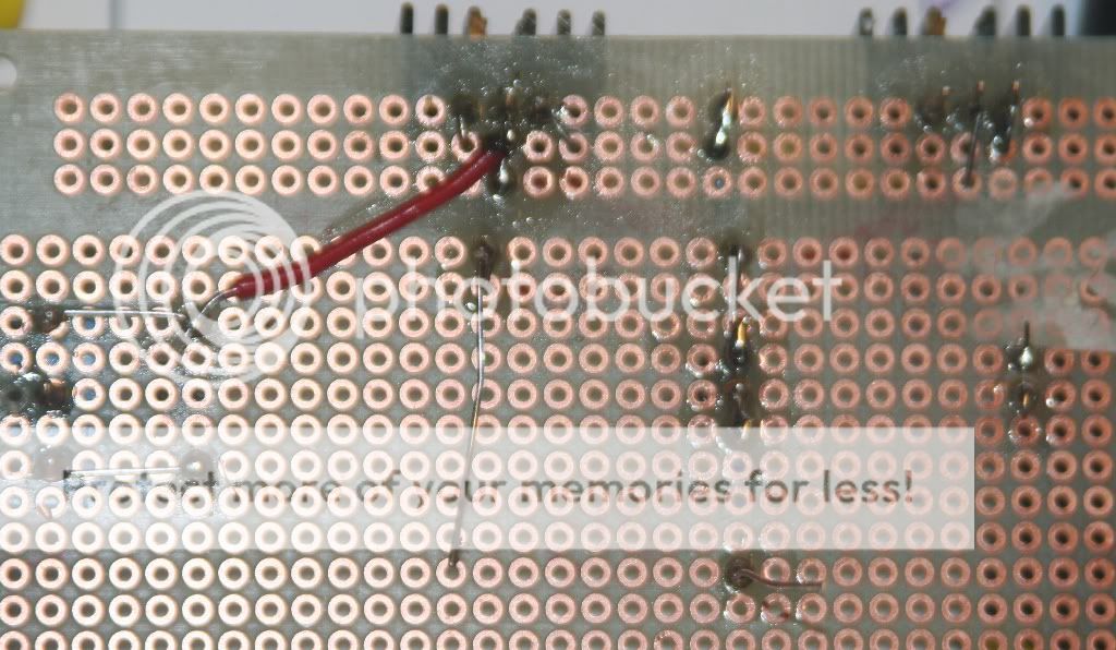
Left to do is solder in the LED's, GND rail, rectifying and connectors(also connect the 100nF wima).
Might not be pretty, but there's connection where it should be and no shorts.
Left to do is solder in the LED's, GND rail, rectifying and connectors(also connect the 100nF wima).
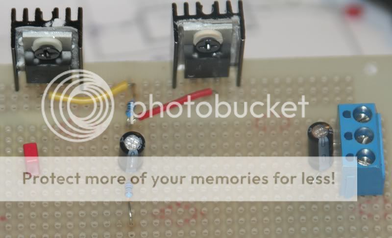
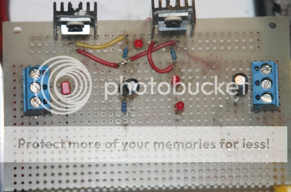
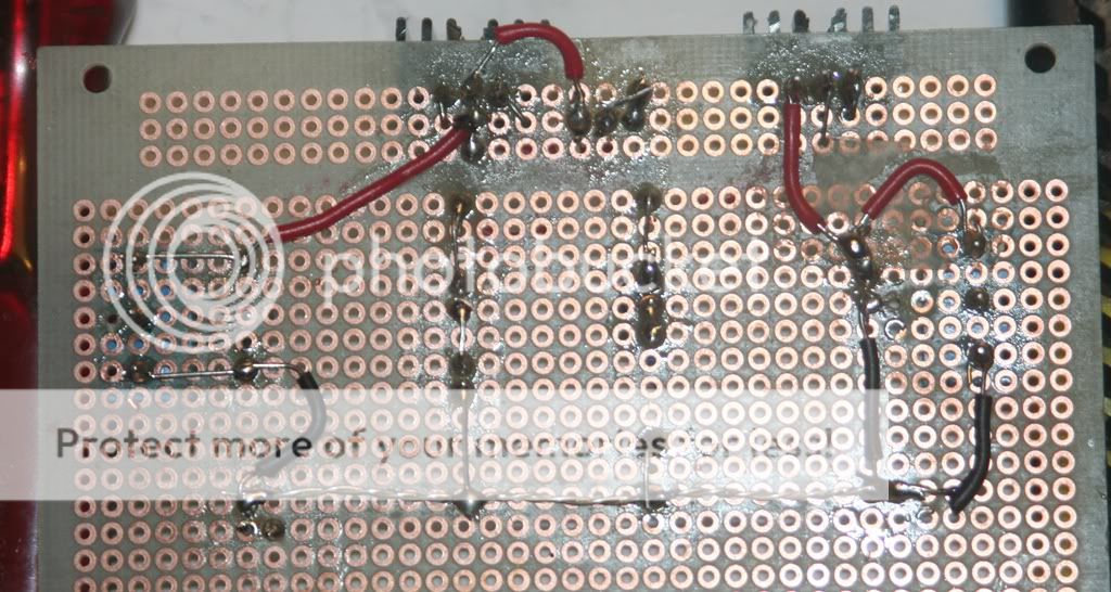
Done!
Some flux-cleaning and trimming the bord left.
As you can see there's plenty of space for bigger heatsinks 🙂
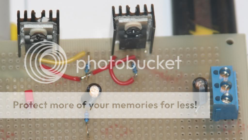
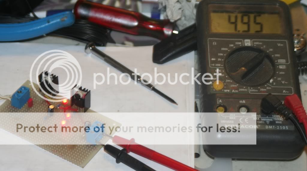
Test setup
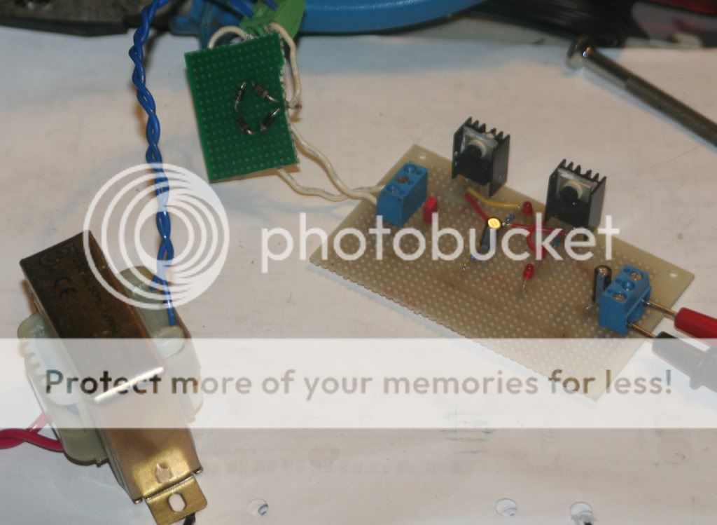
Result 😀
Some flux-cleaning and trimming the bord left.
As you can see there's plenty of space for bigger heatsinks 🙂
Test setup
Result 😀

Does the dog do the vacuuming too ?
Like....bits of wire and solder blobs on the floor ?
Send him here when he's finished😀
Like....bits of wire and solder blobs on the floor ?
Send him here when he's finished😀
Does the dog do the vacuuming too ?
Like....bits of wire and solder blobs on the floor ?
Send him here when he's finished😀
Could be a mess on the floor when I'm done for the day, but no HE doesn't vacuum, in fact he doesn't like the vacuum 😀
He's a great watchdog though, imported, from protection/work breeding. A big one for a Dobermann too 76cm floor to back and nearly 50kg.
A shame we can't compete with him in events like protection etc due to him being cropped and docked(spelling?) which isn't allowed in Sweden. It was done by the breeder who lives in a country where it's legal.
My fiancé is the one who most of the time fixes the mess I make when DIY:ing 😱
Last edited:
Btw, what are you doing up so late Andrew???
Aren't you the one telling me to get some sleep? 😉
Aren't you the one telling me to get some sleep? 😉
oops...send HER here I mean !
The "she" you're refering to is my 9 year old purebreed pitbull named Foxy, the one in the pic is our 3 year old Dobermann named "Danton" called Dani.
Btw, what are you doing up so late Andrew???
Aren't you the one telling me to get some sleep? 😉
...does ' wrapping bloody presents ' mean anything to you ?
Yep, my job again.🙁
I'm off now

...does ' wrapping bloody presents ' mean anything to you ?
Yep, my job again.🙁
I'm off now
Yes, something the store or my fiancé does 😛
Me to in a bit, just going to finish watching a movie.
Lmao!!!! Too much wine Andrew???
Mayday, nice work. Now all you need to do is get it small enough to use I side the player. Have you tested with a higher voltage transformer and varying load to make sure it's actually regulating?
On the subject of smaller boards, you can use verodes to design the layout it's pretty good 🙂
Mayday, nice work. Now all you need to do is get it small enough to use I side the player. Have you tested with a higher voltage transformer and varying load to make sure it's actually regulating?
On the subject of smaller boards, you can use verodes to design the layout it's pretty good 🙂
Lmao!!!! Too much wine Andrew???
Mayday, nice work. Now all you need to do is get it small enough to use I side the player. Have you tested with a higher voltage transformer and varying load to make sure it's actually regulating?
On the subject of smaller boards, you can use verodes to design the layout it's pretty good 🙂
Thanks!
It's feed w about 12,5Vdc (9Vac, diodebridge) in the picture and giving exactly 4,95Vdc.
That should mean it's regulating, right? Will test it with a 100R 3W resistor load I've got just for this.
I was actually thinking I'd just trim about 10mm of one side of the board and use it as it is.
What's verodes?
Last edited:
I guess so??????
Verodes is software that you can use to plan component layout on veroboard.
Was adviced to put atleast 1000uF after diodes on rectifierboard.
Will use BYV95A diodes.
Installed Verodes, had to fix a few things since I'm running win7.
I'll measure it later today using a 100R 3W resistor as load, if it still gives 4,95Vdc it should be fine. 🙂
How much current will that draw? I think you'll find 0.25w will be enough!
What value cap are you now using after the diodes in the player? That will give you an idea of what you should be using on this psu!
What value cap are you now using after the diodes in the player? That will give you an idea of what you should be using on this psu!
How much current will that draw?
What value cap are you now using after the diodes in the player? That will give you an idea of what you should be using on this psu!
About 50mA(if you are talking about the dummy load), I've already gotten the 3W resistor. If I want to test with full load, I got the advice to use a 27R resistor.
The standard caps are still there, except for the 22000uF TSU.
The other three I'll parallell with 1000uF low esr each.
I've got a few 2200uF good quality caps, could use one or two of those on the rectifier board.
- Status
- Not open for further replies.
- Home
- Source & Line
- Digital Source
- Marantz CD-50 and CD-60, TDA1541, CDM4/19