Please replace that with +-27.5vdc or less
Can't you read english?
Now I know, you can't write english.You said +-30 abs max. I said +-27.5 abs max.
Alright Andrew there is no need for that!!
I appreciate Daniel's assistance and I'd like him to keep writing.
I appreciate Daniel's assistance and I'd like him to keep writing.
That wasn't a secret, but would you help me out with the PI filter safety current limit idea? I wish to rob power from clipping and block some noise at the same time. Apparently, the CRC with the bigger "R" can do it for very durable LM1875 guitar amplifiers to improve clipping performance, such as less noise. What is an estimated ballpark value for "R" if I didn't want LM1875 to be the weakest link?Now I know, you can't write english.
I like Andrew a lot, and I understand that his negative responses are usually in proportion to and related to the severity of an error that I have made. In this case, anything vague or inexact, when it comes to power and current, is indeed a potentially hazardous sort of error in writing. I can't argue with that at all. Therefore, please validate any of my posts, by comparing with other sources, prior to building the circuits.Alright Andrew there is no need for that!!
I appreciate Daniel's assistance and I'd like him to keep writing.
One popular source is Decibel Dungeon and here's a link to it: Building a Gainclone chip amp power supply. <--link
On that page you find this: "Somebody wrote to me suggesting that the 1875/6 chip will last longer with the following settings:"
Those are my long term test findings for real LM1875 chips. They didn't include highly reactive loads as severe as double 10" woofers or 15" woofers or extraordinarily difficult to drive crossovers; because, I didn't have such things during the long term test. AndrewT's post #6 indicates the need for triple parallel LM1875 for such highly reactive loads. For large/difficult speakers, Parallel TDA7294 is also a contender and it can be built with the point to point method in post #18, resulting in a very similar audio performance, actually imitating the LM1875. I'm actually saving the larger amp for later, for after I have the bridging adapter up and running.
Not me. I do not have a high fidelity LM3886 kit, design, or project demo. However, a high fidelity LM3886 kit exists. . . The MyRef C is a unique fully optimized support circuit for LM3886. I am not the designer, but there is no need to design it. The boards are currently available.Got a good link for building your LM3886 kit?
I have PCBs? Okay, that's fine. Several people have the rights to produce my two LM1875 designs. But I really don't have any PCB's personally.Thanks for the reply Daniel.. . . I've built your 1875 amp and thought the parallel implementation would be something that would use your PCBs.
With a circuit board or the absence of a board, most of that difference is merely visual. When the performance and layout are good for a single amplifier, you can use it for parallel amplifiers if you like. You'll need to add the 0.22R ballast resistors to the outputs. You'll need to measure all resistors to make sure that the two amplifiers are exact copies (resistor matching). Some extra review of star grounding may be necessary. Grounding follows a general "Once met" idea to avoid ground loops.
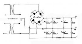
Transformer and rectifier is one easy section:It's interesting that you mention using an array of smaller caps for the power-supply. I was trying to figure out a way to do that with my 1875 amp yesterday!
Check Mark Houston's Synergy Gainclone.
Check the datasheet for KBPC2504 or KBPC1604
Check Decibel Dungeon transformer explanation
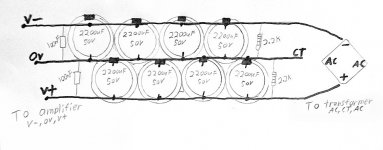
Example power smoothing board another easy section:
12 caps (2 100nF polyester dip caps, 10 pack of 35v 2,200uF ecaps) on copperless phenolic perfboard (no pads, just non-conductive board with holes), and it has this arrangement.
v+, 100nF, 2,200uF, 2,200uF, 2,200uF, 2,200uF, 2,200uF, rectifier +
0v---------------------------------------------------------- CT
v-, 100nF, 2,200uF, 2,200uF, 2,200uF, 2,200uF, 2,200uF, rectifier -
The rectifiers that we are using have clearly marked polarity--KBPC1004 on Mark Houston's example is even better in that respect. The power smoothing section is easier and faster to assemble on a board. I cannot give you a great deal of advice on power supplies, but I can provide photos. Please look up the relevant materials on the Decibel Dungeon website and also Rod Elliot's website.
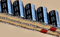
Here are some power supply photos:
Attachments
Last edited:
Oops...
I thyought you has a hand in this:
http://www.diyaudio.com/forums/chip-amps/122793-finally-made-lm1875-amp.html
Thanks for the links. I have some research to do.
Mark Gilbert of Blue Circle is powering a preamp with energy stored in caps only.
I thyought you has a hand in this:
http://www.diyaudio.com/forums/chip-amps/122793-finally-made-lm1875-amp.html
Thanks for the links. I have some research to do.
Mark Gilbert of Blue Circle is powering a preamp with energy stored in caps only.
That amplifier is not one of my designs. It is the datasheet example in LM1875.pdf by National Semiconductor. <--links The chipamp.com LM1875 is a highly usable kit that many people like. Most often they use the board and then simply transplant a favorite design onto the board. There's a couple of threads here on diyaudio.com about enhancements and upgrades for that kit.Oops...
I thought you has a hand in this:
http://www.diyaudio.com/forums/chip-amps/122793-finally-made-lm1875-amp.html. .
The chipamp.com LM3886 kit, which was produced much earlier, is most definitely not an optimized support circuit for LM3886, but rather a low components count model with many omissions. So, if you wanted a hi-fi LM3886, I would suggest using the MyRef materials instead. The cost is similar, the results much different. The tone of the MyRef is same as the source. The sound field cast of the MyRef is both deep and wide, which is a characteristic of a high end amplifier.
Resources:
http://www.diyaudio.com/forums/chip-amps/54571-my-audiophile-lm3886-approach.html
http://www.diyaudio.com/forums/chip-amps/134726-new-my-ref-rev-c-thread.html
http://www.diyaudio.com/forums/chip-amps/167458-myrefc-build-guide.html
http://www.diyaudio.com/forums/group-buys/160768-myref_c-ultimate-bom.html
Last edited:
Ahhh...
I've been looking for a way to buy the MyRef PCBs the past few days but I've searched the threads until my eyes were bleeding and could not find them ready to buy. I did learn who to PM for info.
Twisted Pear Sympatico looks interesting.
I've been looking for a way to buy the MyRef PCBs the past few days but I've searched the threads until my eyes were bleeding and could not find them ready to buy. I did learn who to PM for info.
Twisted Pear Sympatico looks interesting.
Last edited:
Soundfield size as applied to LM1875 parallel
Siegfried Linkwitz, at Linkwitz Lab - Loudspeaker Design <--link speaker methods forces the width cast feature from speakers by using open back and other speaker types know to cast a wide soundfield. These are ever so nice in addition to LM1875's high resolution depth cast (depth is a function of resolution and fore-aft location a function of impedance). With the big dynamics, clarity and the level response of most AC Coupled LM1875 Parallel, together with a wide cast speaker, even a regular stereo pair replicates a concert, successfully scaled to fit into a room.
Linkwitz also shows how to use multi-channel arrangements in his own home. Perhaps he is busy and constraining stereo to a single center point chair is not suitable? Multichannel lets you wander around or sit anywhere without losing the imaging totally. But, it can slightly compromise the imaging point of that central "listening chair" Nevertheless, adding more speakers is a creative way to more plausibly replicate, replay, or produce a concert.
LM1875 amplifiers are also good for arrays, such as "ranks of speakers," whereby you simply stack as many as necessary until you cannot withstand turning the volume control far enough to cause clipping. With modest size parts and acoustic coupling, even a little modular system is easily expandable and powerful. However many kiowatts you need simply depends on however many you stack. Main benefit: No individual speaker is stressed, and thus the array technique doesn't distract by forcing attention to center on speaker boxes.
Last edited:
Linkwitz also shows how to use multi-channel arrangements in his own home. Perhaps he is busy and constraining stereo to a single center point chair is not suitable?
Daniel, I think that you should go back and read Siegfried Linkwitz's papers slowly and carefully again. You totally missed what it's all about.
I believe that Linkwitz turns his center channel on or off depending on if it useful for a given recording. Yes, my statement there was sort of badly phrased. Probably, I should have said that the center channel can help with more flexible seating arrangements. It can also "focus" some recordings that seem to have no middle. The center can re-create the missing stage sound. And the added speaker gives additional impact. There is a variety of uses.
For this thread, I was actually a bit more interested in the construction of his speakers. They give a fairly wide presentation.
I made an Ohm Walsh clone a long time ago and always though it unfocused. . . until the day I connected it up to an LM1875 amplifier with its opposite characteristic. That came out well balanced, neither a hallway shape nor scattered. It drew no attention to the actual location of the speaker. This is much more compact than array solutions and although the power output was at lower scale, the size of the presentation seemed as large as an array solution. . . well, any that would have fit into the room. Perhaps the ribbon tweeter helped a bit.
I don't think so. Siegfried Linkwitz main interest is in well recorded spaced microphone serious music. Pan potted multi-microphone recordings need not apply.
It's a lot of reading but start here:
AS_creation
It's a lot of reading but start here:
AS_creation
Again, I am far more interested in his open back speakers and wish there were ribbon tweeters combined with open back speakers like those; however. . .
Linkwitz Surround stereo system at his home.
According to the link, there is a minor flirtation with center channel for whenever it benefits the recording. Yes, you are correct that the main focus is on the recording.
Unfortunately for realism, I think that his integrated receiver was lackluster in the design of the center amp. I have to wonder why so much attention on speakers without the same sort of attention to the amplifier? The effect should have been impressive and astonishingly large, and it seems as though the mass market amplifier failed miserably in that regard. It is a credit to his speakers that the approach was intelligible.
http://www.diyaudio.com/forums/chip-amps/120616-lm1875-pcb-use-4.html#post1696460
All over that thread is LM1875 optimizations, discussions, schematics and opinions.
It is my intention to show an assembly method. You can use any schematic you like. Some of the charms of the LM1875 is that you can build your own thing, with quick success, high resolution, and minimal cost.
For parallel, add 0.22 ohm 3W or better resistors series with the speaker output of each chip. This small resistor loss is common to most parallel amplifiers so that they don't fight.
Resistor matching is necessary for parallel amplifiers.
Measure all resistors with digital ohmmeter to be sure that:
all feedback resistors are identical
all feedback-shunt resistors are identical
all stopper resistors are identical
all input load resistors are identical
Thanks, but I was not asking about the schematics for the single chip per chanel.
I have such schematics, that is available everywhere, I made quite a few of those amps with original Nat Semi schematics from application list.
I was asking about parallel chip per chanel, isn't what this thread is about?
I thought that you figured out how to share resistors and capacitors by both chips. That wat you do not need to measure and match the values. Oh well, never mind.
You have a two part answer for that one.
1).
The following cannot be shared: Stopper resistors, feedback-shunt resistors, feedback resistors, and output ballast resistors.
These are required parts to make and to parallel 2 amplifiers. They actually need the resistors on both chips as it looks like a "resistor mixer" and the whole thing looks like a 50/50 divider. Precision resistor matching, by ohmmeter, reduces heat dramatically, and this chip has a small size thermal interface. A parallel amplifier is supposed to be just like a greater number of ordinary amplifiers, because that is what the term means.
2).
However, the input filter capacitor and input load resistor can be shared amongst the two amplifiers if both chips have their own 1k (maybe as low as 470R but definitely not omitted) stopper resistors at the chip input, as per the datasheet.
If the feedback-shunt resistors are more than double the datasheet's values (aka 2.7k has less than half the current as 1k), then is possible that they might share a single NFB cap for their ground reference. Sharing parts like that puts additional demands on good layout, and it actually takes more attention to detail, not less.
P.S.
The assembly method posted can help you deal easily with the many pins of TDA7293V and TDA7294H which can both be paralleled in slave mode, meaning possible to do it without output ballast resistors. But that is not an example of parallel amplifiers--instead, the "slave mode" is an example of parallel output devices, more like a discrete amplifier with fet outputs.
Last edited:
hi danielwritesbac,
so basically you suggest this:
DIY Audio Projects Forum • Triple Parallel LM1875 amplifier
so basically you suggest this:
DIY Audio Projects Forum • Triple Parallel LM1875 amplifier
adason - thats here buddy
http://www.diyaudio.com/forums/chip...riple-parallel-lm1875-dynamics-amplifier.html
i started that thread on the diy audio projects forum in addition to the one here, as some members here are not members there 🙂
http://www.diyaudio.com/forums/chip...riple-parallel-lm1875-dynamics-amplifier.html
i started that thread on the diy audio projects forum in addition to the one here, as some members here are not members there 🙂
More to the point if the current thread: Our little double-parallel is much easier. Simply make one good LM1875 amplifier, copy it precisely to make another, and then put 0.22R on the outputs of both. Just avoid ground loops with the thought "once met" as a general rule. The double parallel can withstand approximately 8" 4 ohm speakers or dual 6" 8 ohm speakers (your favorite little MTM), or bridging for up to 8" 8 ohm speakers, or so, as long as it is easy to drive and that the crossover inductor has significantly dropped the load of crossover shunting components.
Dynamic loads: It is not compatible with hard to drive erroneous crossovers and/or shoving enormous size cones. That would take significant derating. Perhaps this Parallel amplifier could drive an 8 ohm 15" woofer to 20 watts. However, it isn't made for that task.
Little bridge: The main purpose of the amplifier on this thread is the smallest, least complicated, cleanest (no internal gimmick features) little op amp available to directly drive a medium to modest size 8 ohm speaker, in order to test and learn about various means of bridging.
Other educational features include star grounding as it applies to chassis layout--since there's no amplifier PCB, there may be more concentration on good cable layout in the chassis.
MTM, WWT: As a side effect, if it is NOT bridged, then it is able to drive some of the cute little dual 8 ohm 6" woofer WWT and MTM speakers that are currently popular, have a low cost crossover (single inductor sized for 4 ohm), double impact, and need a little parallel amplifier that doesn't run too hot. Despite the cute size, low cost and minimal effort, output can be fairly prodigious, depending on speaker efficiency, of course. For that sort of system, the main focus is the word "doable" and not necessarily an efficient arrangement, but rather, an easy arrangement. Of course, efficiency helps dramatically, but doable is even more important. That may be one of the easiest ways to get sufficient power, high resolution, and a level frequency response, all in one package.
Last edited:
- Status
- Not open for further replies.
- Home
- Amplifiers
- Chip Amps
- Parallel LM1875, 2 chips per channel, in 5 minutes ea? Can bridge if 8 ohm speakers.