I also have Mundorf .22uF Zn that I will try. Why would a larger cap hurt? unless its part of a filter, I always thought bigger is better.
To really say bigger in this filter you go to elcap. And there is position. Just try your filmcaps there and see if you can have a preference.
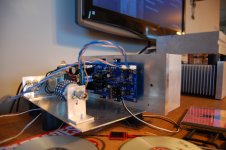
Fired it up last night and have some issues. First set of LEDS do not light up and there are 6V dropping across first mosfet Rs. No vltage across the 100R resistors of the sk170 ccs. Does this point to bad Jfet or something with mosfets? Other LEd's light up and are looking good in their operation so it seems that i am having trouble with my current setting section.
Which half of the dual polarity supply is not working as expected?
Post a schematic showing the errant voltages of the non working half.
Post a schematic showing the errant voltages of the non working half.
How crucial is film cap value. I have .1uF Mkp1837 and 1uF Clarity cap.
Try two MKP1837's in parallel; they worked extremely well in my two builds.
Buzz, make sure the LED's are not in backwards there. Easy mistake.
You should be able to diode tester across there, and one way other get some voltage reading, light or both.
You should be able to diode tester across there, and one way other get some voltage reading, light or both.
THe voltage regulation section of both halves is working, it is the current regulation part that is not. Both sets of 5 LEDs are lit up and well balanced and I am getting 10.43+ and 10.41- to the actual buffer section. THe triplets controlling both + and - current setting function are not lit up and I am not getting anything across the 100R resistor to ground. I am dropping almost 6V across the dual 47R current setting resistors on both rails. 17V in to this area from rectifiers. The LEDS are oriented just like the ones that are working properly in the voltage stage. It would seem with the numbers I am getting that the 2sk170 ccs is not proving any current to the diodes. anoter oddity is the fact that the LED to delay circuit is not lighting up even though you can hear the relay latch, which would suggest that it is working.
I assume it was probably answered before...does this film cap affect on sound? I now have Wima MKP (from Tea-Bag kit) and wondering if it's worth to upgrade to something more exotic. Or should I just tra to bypass with MKP1837?
I just realized in typing that the LEds are incorrect. Nwly installed LED in delay section was not working even though the relay was latching. I have anode in square and cathode in round hole. THis is incorrect but for some reason the voltage control section is lighting up.
I assume it was probably answered before...does this film cap affect on sound? I now have Wima MKP (from Tea-Bag kit) and wondering if it's worth to upgrade to something more exotic. Or should I just tra to bypass with MKP1837?
Its a bypass cap for the LED's that is by nature there to help with noise I believe. How much affect different caps have in that position is up to your ears.
I referenced another board to determine positioning of LED's. Although it had the diode symbol, I did not pay attention to that and was paying attention to square vs round pcb hole. It just so happens that they arranged their anode as square hole and cathode as round hole, just the opposite of the DCB1. Now the leds are switched and all is good. -2mV offset on both channels. This is now paired with BA-3 FE and BA-3 output with 2 pairs of lateral output fets, biased at .75A per fet. It sounds wonderful. I cant wait to crank the bias up from 60mA to 200mA and then on to 600mA.
woodturner-fran did the most extensive listening test with different values, and found .22uf to be a good spot, and a lot of us followed that example.
If I had to choose for you, the MKP1837 would be my choice, measure well and well regarded.
Hi Tea-bag,
How about the MKP1839? Is that any good? I have a few of them and plan to use on the DCB1.
VISHAY ROEDERSTEIN|MKP1839410164|CAPACITOR AXIAL, MKP, 100NF, 160V | e絡盟 Hong Kong
I referenced another board to determine positioning of LED's. Although it had the diode symbol, I did not pay attention to that and was paying attention to square vs round pcb hole. It just so happens that they arranged their anode as square hole and cathode as round hole, just the opposite of the DCB1. Now the leds are switched and all is good. -2mV offset on both channels. This is now paired with BA-3 FE and BA-3 output with 2 pairs of lateral output fets, biased at .75A per fet. It sounds wonderful. I cant wait to crank the bias up from 60mA to 200mA and then on to 600mA.
Happy end. Congratulations.🙂
Hi All,
My preamp just went dead recently and I'm considering building a DCB1 as my new preamp. I currently have a UCD400 power amp. Do you think a balanced DCB1->UCD400 would be a good combination? I have searched several threads but seemed not see this combination in any discussion... Please let me know if you think there might be any problem with them.
Also, I have an UCD softstart module that I plan to use on DCB1. Would there be any problem in doing so? Thanks a lot!
Ijust turned up the bias to 750mA. Wow! Everything is clearer with more body and grunt. Softer but clearer somehow. Based on what i am hearing, i will try 1A bias and maybe even 2A. I would turn up the bias before spending a lot of money on parts of an exotic nature. I tried multiple caps and nothing compared to the change brought about by more bias. I have them on a 4" high 10.8 heatsink from HeTsink USA, and they arent even sweating with plenty of room for more. Salas, phenominal job!
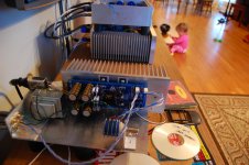
The heatsink is overkill. I could probably mount directly to 1/16" bottom and be fine. Did it to try higher bias setting. Will try higher bias soon.
I am reminded of John Curl talking abbout how much time he put into his psu and regulatr section. This makes me a beliver.
I am reminded of John Curl talking abbout how much time he put into his psu and regulatr section. This makes me a beliver.
Last edited:
- Home
- Source & Line
- Analog Line Level
- Salas hotrodded blue DCB1 build