Gents.
I'm giving 6 a weekend off .... Sounds like he's having tons of fun .
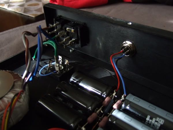
Anyway , this Cardas grnd connector I have ... Should it be isolated from the real chassis panel ?
Thanks ,Rich
I'm giving 6 a weekend off .... Sounds like he's having tons of fun .
Anyway , this Cardas grnd connector I have ... Should it be isolated from the real chassis panel ?
Thanks ,Rich
Oh so is that the same problem that Rich had ?
So I understand better, if IDSS of the K170BLs are a little high then Q3 gets "on his knees",
so an adjustment is needed via R9 to get about 9 to 10V on jfet drains.
nAr - Yes indeed, it is possible Rich is having the same problem I had. I guess it is desirable for Q3 to be biased so that Vce is at least one volt (giving forward bias). Whether this happens at 5, 10 or 15 volts is probably not a big deal.
Rich - You could try putting a 1k ohms in parallel with the 499 ohms, then measure voltages around Q3. While you are at it, check the voltage across the 10 ohm of each jfet. Mine measure close to 75 mV hence 7.5 mA and they seem to be happy.
Pierre
Last edited:
When I posted my last entry, I was quoting voltages from memory... I have + and - 47v .
Again, hopefully a little load and the last RC stage will bring it down, but I bet that I will have to change the resistors... Not a big deal, I just need to finish wiring the RIAA box to hook everything up and see.
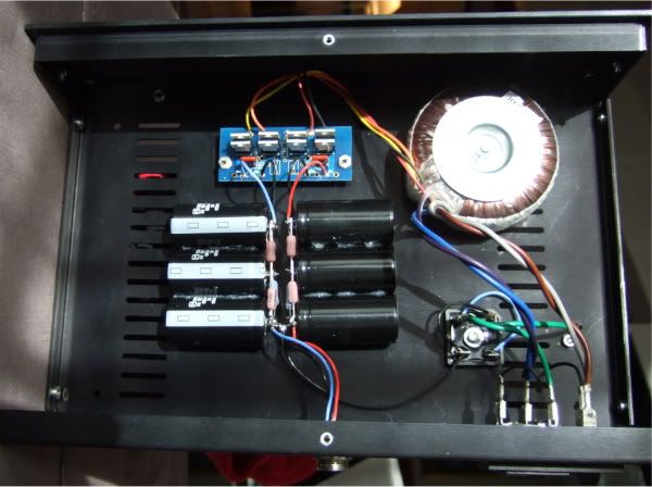
Here are a couple of fairly uninteresting photos -
Again, hopefully a little load and the last RC stage will bring it down, but I bet that I will have to change the resistors... Not a big deal, I just need to finish wiring the RIAA box to hook everything up and see.
Here are a couple of fairly uninteresting photos -
In case this is of any help, I measure the drop on the two 10 ohms to be 0.26v on the positive side, and 0.11v on the negative side.When I posted my last entry, I was quoting voltages from memory... I have + and - 47v .
Last edited:
Yeouch! .2v? I need more resistance...
What is the current draw you were using for computation?
Any good guess for a resistor(s) value? I would ideally like to be well under 40v, perhaps 32 or so?
What is the current draw you were using for computation?
Any good guess for a resistor(s) value? I would ideally like to be well under 40v, perhaps 32 or so?
What is the current draw you were using for computation?
Any good guess for a resistor(s) value? I would ideally like to be well under 40v, perhaps 32 or so?
Computation? Those voltages are from my voltmeter 😉.
Based on your Q3 measurements, your front-end jfets draw less than mine. To land around +/- 35 volts, you may want to start with 375 ohms for the positive supply, and 500 ohms for the negative. I don't see a down side dropping voltage that way.
You should use 2 or 3 watt resistors. If for some reason you want to use 1/4 or 1/2 watt resistors, spread the load. At a minimum, parallel four 1.5k for the +, and two 1k for the -. They will run hot. Leave air space around them.
Ah. My (unregulated) PSU is different, as I'm starting with a 30+30v transformer...
Here is how it's built right now -
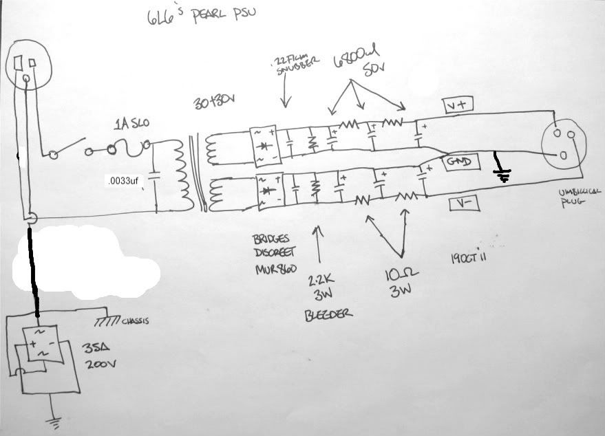
Here is how it's built right now -
nAr - Yes indeed, it is possible Rich is having the same problem I had. I guess it is desirable for Q3 to be biased so that Vce is at least one volt (giving forward bias). Whether this happens at 5, 10 or 15 volts is probably not a big deal.
Rich - You could try putting a 1k ohms in parallel with the 499 ohms, then measure voltages around Q3. While you are at it, check the voltage across the 10 ohm of each jfet. Mine measure close to 75 mV hence 7.5 mA and they seem to be happy.
Pierre
Nice catch, let Rich the time to try the mod whilst adding jfets ... I guess mine were lesser IDSS, so I didn't run into that problem 😉 Better chack again soon, next time I open the lid to make some maintenance 😉
When I posted my last entry, I was quoting voltages from memory... I have + and - 47v .
Again, hopefully a little load and the last RC stage will bring it down, but I bet that I will have to change the resistors... Not a big deal, I just need to finish wiring the RIAA box to hook everything up and see.
Here are a couple of fairly uninteresting photos -
Nice cases and work 😎
You could also drive the xformer with less voltage at mains. Maybe a drop on mains with an R could give you 40V. Which is your mains voltage here ?
Best,
nAr
Just added Q7 ... 3.06 vdc Top , 4.11 vdc .... I need 10 ish ?
have you tried R9 mod as Pierre said ? which V on jfet drains now ?
Best,
nAr
have you tried R9 mod as Pierre said ? which V on jfet drains now ?
Best,
nAr
Hi nAr,
no I have not tried that ... I think I need to concede defeat here and ask for direct intervention . 6 and I must have spent 15 hours over the past 2 weeks trying to get this thing to work .
I really need to ask if there is anyone that would be good enough to take a look at these boards for me . I don't have a ton of cash ,but I would be willing to pay someone something for the help .
I can't get the P1 even close to zero . I get nothing ,but a static sound when I test it with a signal .
I don't have scope . I just have too much money in this project to walk away . I don't like quitting ,but I do know I'm out of my depth with this .
F^*&^*^)*( IT . I'm sick of looking at it !
Rich
Rich
you have to be patient, getting 1st stage working properly without 2nd stage.
In case, remove all active devices of 2nd stage or biasing resistors for 2nd stage
from v+ v- to work on 1st stage alone.
Best,
nAr
Last edited:
If you want to adjust bias on Q3 it is best to adjust R10. R3 is part of the equalization network. I may have suggested the wrong resistor.
power supply voltage can also be dropped with some 5W zeners as part of the CRC filter network. Ten Ohms caps 100 Ohms 39 volt Zener. a little fiddling and this should get you a shunt regulator feeding the 24 regs.
power supply voltage can also be dropped with some 5W zeners as part of the CRC filter network. Ten Ohms caps 100 Ohms 39 volt Zener. a little fiddling and this should get you a shunt regulator feeding the 24 regs.
Hi nAr, merci !
remove P1 , Q5,Q2, Q10,Q11,Q4 ?
Rich
Yes. And see how 1t stage goes by Pierre suggestion ... 4 fets with 9-10V @drain = target
Best,
nAr
remove P1 , Q5,Q2, Q10,Q11,Q4 ?
Just Q10 and Q11 will do.
Ok, I have P1 and the led in the output stage and just 1 fet ( at the moment in the input )... i'll check the voltages then put the other 3 back in and post the voltage in the morning .
Rich
Rich
If you want to adjust bias on Q3 it is best to adjust R10. R3 is part of the equalization network. I may have suggested the wrong resistor.
Oh... You mean that the resistor at the collector of Q3 (R9, 499 ohms) plays in the RIAA filter? We don't want to mess with it then!
Got it, I should have lowered the voltage at the base of Q3 through the resistor between its base and ground (R10, 10k).
Am I ever glad I asked 😛
Done. I put R9 back to 499 ohms, and lowered R10 from 10k to 3.22k. This biases Q3 at Vc=5.1 > Vb=4.4 > Ve=3.7.
- Home
- Amplifiers
- Pass Labs
- Pearl Two