The back pressure in a sealed box doesn't contribute to the radiated power, so is not relevant when looking at "mutual coupling" between the front of two drivers, which serves to increase the radiation resistance and increase efficiency.That flies in the face of both theory and practical experience. The back pressure wave of one driver directly affects the others, far more so than what's in front of the driver which is in the external air where the change in atmospheric pressure locally is much smaller.
If you compare a single woofer in a closed box to two side by side woofers each in identical closed boxes, because both are trying to push outwards at the same time, each sees a stiffer air load due to the localised pressure increase caused by the opposing woofer. This transfers energy from the cone movement to the room air more efficiently.
All I can say about this is that you are dead wrong and had better check your references again, as well as any Thiele/Small box modelling program that supports multiple drivers.Proof? Two AR3 type woofers in separate enclosures have an F3 of 42 hz individually or in adjacent pairs. Same two drivers in a single double sized enclosure, AR9 have an F3 of 28 hz. See Tim Holl's excellent writeup in CSP's Library.
To get the same bass alignment with two identical woofers sharing the same box you need twice the box volume of the single driver case. (But the payoff is a 3dB efficiency increase for the same cutoff frequency and alignment)
Let me offer you a simple thought experiment. Imagine a large cylinder with a woofer mounted at each end facing outwards. Both woofers are wired in phase so they both move out together.
What happens to the air in the tube when both woofers are moving inwards and the air is compressed ? A velocity gradient will form along the tube where the air at the very middle is not moving - it's the centre locus of the compression if both drivers are identical.
Now place a baffle right in the middle to divide the cylinder in half. What happens to the tuning of the speaker ? Nothing. (Apart from a tiny shift due to lost volume from the thickness of the baffle)
This is exactly the same as a closed box shared by two woofers, at least at frequencies that are low compared to the box dimensions. (Typically all bass frequencies)
I take it you've never tried putting two woofers in the same cabinet before ?
Last edited:
"I take it you've never tried putting two woofers in the same cabinet before ?"
No, I just bought the results of AR's efforts in that regard. As fine a bass producer as the AR1/1W type design is (AR3,3a,LST,10pi,11,303), it's no match for Teledyne AR9. That may be one reason why collectors of vintage AR speakers regard AR9 as the best product they ever produced and prize it so highly. Parts Express just recently introduced a comparable two woofer version of their single driver design.
Dayton Audio RS1202K 1000 Watt Dual 12" Subwoofer Kit 300-766
It looks like it could give AR9 a run for its money.
For small arrays, yes it is just the vector sum. But for larger arrays not so because by doubling and doubling again, and again.... you very quickly find that efficiency at low frequency goes over 100%. 😱 I'm sure Tom can explain this better than me.
Yes, that true. Don Keele covered that in his other paper about the maximum possible efficiency of a direct radiator (which relates to driver area). The issue is that the "insignificant" air load impedance eventually becomes significant and can't be ignored as part of the total impedance. (I think we covered this in the other thread?)
Whether sensitivity climbs without limit, due to d.i. gain, I'm not sure about. I suspect that eventually you have a near infinite plane of drivers and adding a few more million around the perimeter won't make much difference!
Now my brain hurts.
David S.
The back pressure in a sealed box doesn't contribute to the radiated power, so is not relevant when looking at "mutual coupling" between the front of two drivers, which serves to increase the radiation resistance and increase efficiency.
If you compare a single woofer in a closed box to two side by side woofers each in identical closed boxes, because both are trying to push outwards at the same time, each sees a stiffer air load due to the localised pressure increase caused by the opposing woofer. This transfers energy from the cone movement to the room air more efficiently.
All I can say about this is that you are dead wrong and had better check your references again, as well as any Thiele/Small box modelling program that supports multiple drivers.
To get the same bass alignment with two identical woofers sharing the same box you need twice the box volume of the single driver case. (But the payoff is a 3dB efficiency increase for the same cutoff frequency and alignment)
Let me offer you a simple thought experiment. Imagine a large cylinder with a woofer mounted at each end facing outwards. Both woofers are wired in phase so they both move out together.
What happens to the air in the tube when both woofers are moving inwards and the air is compressed ? A velocity gradient will form along the tube where the air at the very middle is not moving - it's the centre locus of the compression if both drivers are identical.
Now place a baffle right in the middle to divide the cylinder in half. What happens to the tuning of the speaker ? Nothing. (Apart from a tiny shift due to lost volume from the thickness of the baffle)
This is exactly the same as a closed box shared by two woofers, at least at frequencies that are low compared to the box dimensions. (Typically all bass frequencies)
I take it you've never tried putting two woofers in the same cabinet before ?
How does one driver in a 1.75 cu ft box end up with an F3 of 42 hz and a Q of .707 while two identical drivers in a 3.5 cu ft box end up with an F3 of 28 hz and a Q of .707? Entirely different crossover networks maybe? Getting two 4 ohm drivers wired in parallel to have a combined impedance of 4 ohms without a major sacrifice in efficiency was a nifty trick.
(Continuing on)
In fact isn't that the case for a vast array of drivers? Once it becomes an approximation to an infinite array, then any distance is in the near field and the response at your observation point becomes the same as the near field response (of one driver?) i.e. the maximum gain of the array is to raise the "far field" to the near field response level?
David
How does one driver in a 1.75 cu ft box end up with an F3 of 42 hz and a Q of .707 while two identical drivers in a 3.5 cu ft box end up with an F3 of 28 hz and a Q of .707? Entirely different crossover networks maybe? Getting two 4 ohm drivers wired in parallel to have a combined impedance of 4 ohms without a major sacrifice in efficiency was a nifty trick.
Perhaps your figures are in error? Simon's scenario is correct.
If I remember correctly, I believe the AR9 uses the parallel woofers only in the regions where the impedance is high, ignoring the 2 ohm mid frequencies.
David S.
Tim Holl's article on the AR9
Engineering the AR-9 by Tim Holl | The Classic Speaker Pages
He paralleled the woofers and put them in a significantly larger box. He then used a tuned network to control the system Q and keep the impedance to a reasonable level.
David S.
Engineering the AR-9 by Tim Holl | The Classic Speaker Pages
He paralleled the woofers and put them in a significantly larger box. He then used a tuned network to control the system Q and keep the impedance to a reasonable level.
David S.
Originally Posted by john k... View Post
For small arrays, yes it is just the vector sum. But for larger arrays not so because by doubling and doubling again, and again.... you very quickly find that efficiency at low frequency goes over 100%. I'm sure Tom can explain this better than me.
As far as the "brain hurting" vast driver array, near field response does not continue to increase when the center to center distance between elements is more than 1/4 wavelength.
The vast driver array near field becomes quite large, and the point where the inverse distance law starts to work is extended some distance forward from the array, dependent on array shape and size.
A current approach to the large woofer array solves the problem of cancellation due to the huge frontal area needed for for 64 18" woofers.
The sub cabinets are flown, two to four cabinets tall, in two "walls" four (or more) deep facing each other. The cabinets are progressively delayed from front to back, the back cabinets with no delay.
This results in an exit area only the area of approximately four to eight cabinets, but the acoustical power of 16 to 32 cabinets.
The progressive delay also increases rear cancellation, so far less bass energy goes rearward than the usual line of woofers across the front of the stage.
Art
For small arrays, yes it is just the vector sum. But for larger arrays not so because by doubling and doubling again, and again.... you very quickly find that efficiency at low frequency goes over 100%. I'm sure Tom can explain this better than me.
In response to John K. "you very quickly find that efficiency at low frequency goes over 100%", no the efficiency does not go over 100%, the directivity increases, the power is concentrated in a more confined area, increasing on axis sensitivity.Yes, that true. Don Keele covered that in his other paper about the maximum possible efficiency of a direct radiator (which relates to driver area). The issue is that the "insignificant" air load impedance eventually becomes significant and can't be ignored as part of the total impedance. (I think we covered this in the other thread?)
Whether sensitivity climbs without limit, due to d.i. gain, I'm not sure about. I suspect that eventually you have a near infinite plane of drivers and adding a few more million around the perimeter won't make much difference!
Now my brain hurts.
(Continuing on)
In fact isn't that the case for a vast array of drivers? Once it becomes an approximation to an infinite array, then any distance is in the near field and the response at your observation point becomes the same as the near field response (of one driver?) i.e. the maximum gain of the array is to raise the "far field" to the near field response level?
David .
As far as the "brain hurting" vast driver array, near field response does not continue to increase when the center to center distance between elements is more than 1/4 wavelength.
The vast driver array near field becomes quite large, and the point where the inverse distance law starts to work is extended some distance forward from the array, dependent on array shape and size.
A current approach to the large woofer array solves the problem of cancellation due to the huge frontal area needed for for 64 18" woofers.
The sub cabinets are flown, two to four cabinets tall, in two "walls" four (or more) deep facing each other. The cabinets are progressively delayed from front to back, the back cabinets with no delay.
This results in an exit area only the area of approximately four to eight cabinets, but the acoustical power of 16 to 32 cabinets.
The progressive delay also increases rear cancellation, so far less bass energy goes rearward than the usual line of woofers across the front of the stage.
Art
The mass and spring analogy falls short here because this would appear to describe a mound or band pass response and it does exactly IF what you’re looking at is the radiator velocity.
The problem is that a woofer is usually on the sloped part of the radiation resistance curve and so to get flat response, the velocity must fall off with increasing frequency. That correction slope is provided by the woofers moving mass of the resonant system above it’s resonance dominating the system.
John Watkinson wrote a short article for Electronics World about a dozen years ago that had a nice set of plots showing the amplitude, velocity, and acceleration behavior(amplitude and phase) of a loudspeaker.
for F >> resonance:
acceleration is in phase with applied voltage, amplitude is 180 deg out of phase
for F << resonance:
amplitude is in phase with applied voltage, acceleration is 180 deg out of phase
This is why when you do a polarity check with a battery and see the cone move outward, the some polarity will give you a positive going impulse response.
This is also why applying motional feedback to a woofer is not as easy as one might initially think.
Attachments
Amplitude (instantaneous position or displacement in the article) is a scalar. It has no direction, just magnitude. Acceleration is a vector. The statement that amplitude and acceleration are out of phase makes no sense.
Amplitude (instantaneous position or displacement in the article) is a scalar. It has no direction, just magnitude. Acceleration is a vector. The statement that amplitude and acceleration are out of phase makes no sense.
All three parameters are vectors...directional sign convention for all three being
(+) for outward position, outward directed velocity, or outward directed acceleration
(-) for inward position, inward directed velocity, or inward directed acceleration
The statement that amplitude and acceleration are out of phase simply means that while the loudspeaker is reproducing a steady tone, and the cone position is (+)(ie outward) with respect to resting position the force applied to the cone by the voice coil is trying to accelerate it in a (-)(ie inward) direction.
The difference in behavior for tones of frequency well above or below resonance is whether the displacement is following the input voltage (+ displacement while + voltage is applied to voice coil) or the acceleration is following the input voltage(+ acceleration while + voltage is applied)
Do you believe only in rectified AC?Amplitude (instantaneous position or displacement in the article) is a scalar. It has no direction, just magnitude.
Having a positive or negative sign does not make a quantity a vector. Minus four degrees versus plus four degrees does not make temperature a vector. Amplitude means magnitude. Scalars have magnitude but no direction. Position only has meaning as a vector only when compared to a reference point. Displacement is another matter, the reference point is the neutral position of the voice coil/cone with no external force applied. The spring constant k will always create force in a direction opposite to the direction of displacement and the velocity related drag constant b will always create a force opposite to the direction of motion. However, whether the voltage is in phase or out of phase with the direction of motion is the result of the net force acting on the coil/cone. It is the motive force acting to direct the motion of the cone. If it is greater than the restoring force at some point it will be in the direction of the cone as the cone catches up to it. If this were not true then the rotary motor analogy would be that a motor would always run backwards relative to the direction of the magnetic field pulling on the armature pole pieces.
Amplitude means magnitude. Scalars have magnitude but no direction. Position only has meaning as a vector only when compared to a reference point. Displacement is another matter, the reference point is the neutral position of the voice coil/cone with no external force applied.
Aah, OK. I didn't catch the discrepancy in the article you were pointing to.
Yes, I agree that the label "Amplitude" on the top plot in Figure. 2 should be "Displacement" as described in the text and the Fig. 2 description.
A little photoshop fix attached...
Attachments

X = real(exp(st)) = cos(wt)
U = dx/dt = real(s * exp(st)) = -w sin(wt) = w * cos(wt-Pi/2),
a = dU/dt = real ( s^2 *exp(st)) = -w^2 cos(wt)= w^2 * cos(wt - Pi)
U = dx/dt = real(s * exp(st)) = -w sin(wt) = w * cos(wt-Pi/2),
a = dU/dt = real ( s^2 *exp(st)) = -w^2 cos(wt)= w^2 * cos(wt - Pi)
Aah, OK. I didn't catch the discrepancy in the article you were pointing to.
Yes, I agree that the label "Amplitude" on the top plot in Figure. 2 should be "Displacement" as described in the text and the Fig. 2 description.
A little photoshop fix attached...
Good thing this isn't quantum mechanics where Heisenberg tells us the more you know about where you are the less you know about where you're going...and visa versa. Him and his buddy Max. One thing I know, I'm never going too far north again.
Originally Posted by john k... View Post
For small arrays, yes it is just the vector sum. But for larger arrays not so because by doubling and doubling again, and again.... you very quickly find that efficiency at low frequency goes over 100%. I'm sure Tom can explain this better than me.
In response to John K. "you very quickly find that efficiency at low frequency goes over 100%", no the efficiency does not go over 100%, the directivity increases, the power is concentrated in a more confined area, increasing on axis sensitivity.
As far as the "brain hurting" vast driver array, near field response does not continue to increase when the center to center distance between elements is more than 1/4 wavelength.
The vast driver array near field becomes quite large, and the point where the inverse distance law starts to work is extended some distance forward from the array, dependent on array shape and size.
A current approach to the large woofer array solves the problem of cancellation due to the huge frontal area needed for for 64 18" woofers.
The sub cabinets are flown, two to four cabinets tall, in two "walls" four (or more) deep facing each other. The cabinets are progressively delayed from front to back, the back cabinets with no delay.
This results in an exit area only the area of approximately four to eight cabinets, but the acoustical power of 16 to 32 cabinets.
The progressive delay also increases rear cancellation, so far less bass energy goes rearward than the usual line of woofers across the front of the stage.
Art
You misinterpreted my comments. I was simply pointing out that the idea the efficiency can increase without limit by increasing the number of drivers is in violation of the laws of thermodynamics.
A complete Bodie plot must show both amplitude and phase angle as a function of time. I've never seen a plot of relative mechanical phase angle as a function of input Voltage phase angle. Usually only "group delay" which is the time delay between applied voltage and mechanical response is given, typically in milliseconds. Generally this is only of interest at crossover frequencies where matching group delays between drivers is of value to those who are deluded that they can build a phase coherent speaker that is not also coaxial. Anyone got any real world measurements?
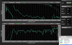
The charts below are a Mackie HD1502 which has built in processing (Gunness Focusing) and is bi-amped using a 1" exit horn on top of a 15".A complete Bodie plot must show both amplitude and phase angle as a function of time. I've never seen a plot of relative mechanical phase angle as a function of input Voltage phase angle. Usually only "group delay" which is the time delay between applied voltage and mechanical response is given, typically in milliseconds. Generally this is only of interest at crossover frequencies where matching group delays between drivers is of value to those who are deluded that they can build a phase coherent speaker that is not also coaxial. Anyone got any real world measurements?
The SH-100 is a Danley Sound Labs 2 way passive crossover 8" coaxial coupled to a shallow "Synergy" horn.
Both speakers are remarkably phase coherent, using quite different design approaches.
The HD1502 is smoother in both phase and magnitude response.
Both speakers sound quite good throughout their horizontal coverage range.
Art
Attachments
John Watkinson wrote a short article for Electronics World about a dozen years ago that had a nice set of plots showing the amplitude, velocity, and acceleration behavior(amplitude and phase) of a loudspeaker.
for F >> resonance:
acceleration is in phase with applied voltage, amplitude is 180 deg out of phase
for F << resonance:
amplitude is in phase with applied voltage, acceleration is 180 deg out of phase
This is why when you do a polarity check with a battery and see the cone move outward, the some polarity will give you a positive going impulse response.
This is also why applying motional feedback to a woofer is not as easy as one might initially think.
This is generally good but I believe the acceleration plot is reversed (should advance at low frequencies rather than retard).
Soundminded said:Amplitude (instantaneous position or displacement in the article) is a scalar. It has no direction, just magnitude. Acceleration is a vector. The statement that amplitude and acceleration are out of phase makes no sense.
The three parameters are being compared to the input voltage. There is obviously a phase difference between displacement, velocity, or acceleration, and voltage. The response shapes alone (lowpass, bandpass and highpass) would suggest a 90 degree phase shift from one to the next and 180 degrees between the extremes. The phase curves (perhaps not the acceleration curve) are simply the Hilbert Transform of the response shapes shown.
David S.
- Status
- Not open for further replies.
- Home
- Loudspeakers
- Multi-Way
- Drivers behave as a mass on a spring...