Ok thank you for information. I'll try them and see. If they'll get too hot, I'll find proper solution. 🙂
Thank you once again. 😉
Thank you once again. 😉
Those Mosfets are tough, I don't expect them to fail easily, but take care that the whole thing develops comfortable box ambient temp when packaged, so its capacitors will live long etc. All things in nature hotter deteriorate shorter.
Of course, in worst case scenario I will put whole board on 10mm thick aluminium block and bolt mosfets on this block and beside mosfets also bolt those heatsink.
Something like this just in my case I'll put those heatsink on this 10mm thick aluminium block.
Something like this just in my case I'll put those heatsink on this 10mm thick aluminium block.
Attachments
No no, I took this picture for example, from Google. 🙂 I think somebody here made this, I remember that I saw this somewhere in this thread.
Better yes. They can handle it in a moderate ambient at 0.6W per TO-220 even alone, but no good long term practice. Since you use the plastic coated ones, a common metal plate to help them, is no insulating hassle.

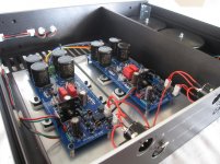
Sure. Who made that tidy balanced DCB1, you?
That's JohnWMclean's awesome balanced DCB1.
See here for more info and pics.
Anand.
Hi Igor,
Salas has done a dissipation calculation for a 150mm tall heatsink.
Your heatsink is a lot smaller. maybe 1.9C/W @ deltaT=70Cdegrees.
Your transformer rated at 50VA 15Vac is effectively rated @ 3.3Aac.
This allows 600mAdc to use just 37% of full rating. It will run cool.
Expect about 22Vdc to 23Vdc at the input to the CCS when set to 600mAdc.
The worst case power dissipation (output shorted) is 0.6 * 22 * 1.06 = ~14W
DeltaT = ~14 * 1.9 * 1.3 = ~35Cdegrees.
Ts ~ 40+35 = ~75degC.
Tc ~ 75+ 1*14 = ~90degC.
De-rate a 120W 150degC device for Tc@90degC and you get [150-90] / [150-25] * 120 = ~58W.
Your worst case dissipation of 14W shows the device can survive due it's de-rated power capability being very much greater (@58W)
You will need to check the actual DC input voltage at the CCS to double check the actual dissipations. Sum the CCS and Shunt dissipations and apply that power @ nominal mains voltage to determine deltaT for the sink during normal operation. It will be very hot, so internal location is probably best. The rest of the circuit will be exposed to all this internal temperature.
Last edited:
Andrew,
Thank you for the thorough response including calculations. It is very easy to understand when the measurements are there and some objectivity is thrown in 😉.
I will also include this link, which was a good descriptor for me, to attend to these heatsink calculations, as they come up often with solid state builds.
Best,
Anand.
Andrew, thank you for calculation.
I messed up things a little. I have 10R resistors and thought those are for 600mA but this morning I went through this thread and found out that 10R is for 200mA hot-rod.
In this case, those heatsinks would be suitable if I'm not mistaken?
Once again, thank you for calculation. 😉
I messed up things a little. I have 10R resistors and thought those are for 600mA but this morning I went through this thread and found out that 10R is for 200mA hot-rod.
In this case, those heatsinks would be suitable if I'm not mistaken?
Once again, thank you for calculation. 😉
Spent a couple of hours with the dcb1 yesterday and everything was good. But today i tried playing some music again and turns out one of the channels died...again. Only this time i didn't unplug any live rca and during yesterday's session there wasn't any loud boom or weird noises like that.
I measured the offset and the absolute values are good, but then i realized something weird - the faulty channel's offset is negative. Maybe it was negative all this while and i didn't realize it. Could that have been the problem?
I measured the offset and the absolute values are good, but then i realized something weird - the faulty channel's offset is negative. Maybe it was negative all this while and i didn't realize it. Could that have been the problem?
Your transformer rated at 50VA 15Vac is effectively rated @ 3.3Aac. This allows 600mAdc to use just 37% of full rating. It will run cool.
Andrew, your math assumes a single secondary.
A 50VA Transformer with 15Vac + 15Vac will effective be rated @ 1.6Aac.
It will run warm.
I am glad someone is awake.
It never dawned on me that Igor could have dual secondary transformer but state 15Vac as the rated output.
If John is correct then the transformer will be run @ ~ double that 37% for the whole transformer. The one loaded winding will be run at ~74% of maximum continuous rating.
Solutions:
a.) reduce the CCS current
b.) parallel the 15Vac windings
c.) Accept that one secondary runs a bit warm and check the surface temperature of the transformer once up and running.
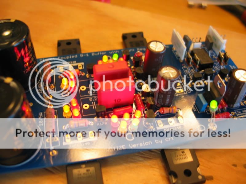
Is this the prettist Christmas Tree you ever did see?
Measured 9.7 and 9.8, waiting for more parts on Friday. Cant wait to listen.
Thanks all..........
Measured 9.7 and 9.8, waiting for more parts on Friday. Cant wait to listen.
Thanks all..........
Is this the prettist Christmas Tree you ever did see?
Measured 9.7 and 9.8, waiting for more parts on Friday. Cant wait to listen.
Thanks all..........
Nice job done Nick,
You have some nice components on that board 😉
Just make sure it’s not on for long without adequate sinking.
- Home
- Source & Line
- Analog Line Level
- Salas hotrodded blue DCB1 build