
10uF film capacitors on PSU?
I had a look at the BA specs and saw that the power supply is very similar to the F4/F5 units. The major difference is the 10uF film capacitor, placed parallel to the last electrolytic capacitor.
In the BA-1 article, Nelson wrote:
"You will also note 10 uF film capacitors across the supply lines. You can delete these, but remember that the prototype used them."
Has anyone tried this on an F4 (or F5)? If so, did it make a difference?
I was thinking of adding a Vishay MKP1839 10uF 160V on each rail for my F4's.
Does anyone have any experience with the MKP1839?
http://www.vishay.com/docs/26022/mkp1839.pdf
Thanks,
Albert
Nice that's right. But not so much beautiful, than mine:Nice library!
https://skydrive.live.com/?cid=e894cb7d50b65fbf#cid=E894CB7D50B65FBF&id=E894CB7D50B65FBF%21172
FQAs arrived
Hi buzzforb,
happy to tell you that the FQAs from Mike Rothacher arrived finally (German Custom ), next week I will try to match them at the F4 current and look what I can send you....
Save three pairs for me, just in case. PLEEEEEEEEEEEEEEEEEEASE. I have two sets of board and will happily do a amp to amp comparison.
Hi buzzforb,
happy to tell you that the FQAs from Mike Rothacher arrived finally (German Custom
), next week I will try to match them at the F4 current and look what I can send you....THanks Generg. I have had my eye on a local supplier. I can pay you or trade you for some Laterals that I will be trying hopefully this weekend. Been out of town past 3 weeks and got very little done other than matching fets.
F4 PSU pictures
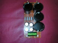
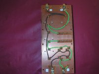
The F4's are coming along nicely. The PSU's are done and I thought I would post some pics of one half of the PSU.
We ended up using a CRC layout with point-to-point wiring:
The journey continues
The F4's are coming along nicely. The PSU's are done and I thought I would post some pics of one half of the PSU.
We ended up using a CRC layout with point-to-point wiring:
- 2 x 15000uF 63V Panasonic THA,
followed by - 4 x 0.47Ohm Panasonic 3W (parallel)
followed by - 2 x 15000uF 63V Panasonic THA
- 4 x 1000uF 35V Elan Silmic II
- 1 x 10uF 160V Vishay MKP1839
The journey continues
Attachments
F4 has two C1, C2 - 220uF capacitors but looking at BA-2 cirquit we can see that there is only one C101 - 1000uF in the same position. So is the C2 a must in F4 then ?
The corresponding C1 is the 10uF from the frontend.
You know normally in F4 2 x 20uF would be sufficient but the 2 x 220uF are there to beware of the turn on and off plopp (as far as I know).
BA-has simply another distribution, the 10uF, this lower value makes a better foil cap possible for the signal path and the big 1000uF for the anti-plopp.
What I always wanted to know but never got an answer...... is this cap is also relevant for the sound.......?
C208 , on BA1 FE and also in BA2 FE schematic ?
if that cap is in question - it is just part of bootstrap mechanismus (R208,R209,C208 on BA1 FE schm) .
plain industrial quality cap is sufficient
if that cap is in question - it is just part of bootstrap mechanismus (R208,R209,C208 on BA1 FE schm) .
plain industrial quality cap is sufficient
Last edited:
Sorry that I was not more clear from beginning......
I mean C101 used in BA-2 value 1000uf
In this circuit version http://www.diyaudio.com/forums/diyaudio-com-articles/194809-burning-amplifier-ba-3-a.html
I mean C101 used in BA-2 value 1000uf
In this circuit version http://www.diyaudio.com/forums/diyaudio-com-articles/194809-burning-amplifier-ba-3-a.html
same approach - that cap is across bias network
some will say that his role is to bootstrap bias network - maintaining constant voltage across it ; Q113,R127,R128,P101
industrial quality cap is sufficient ; for piece of sleep - you can always bypass it with fine MKC
some will say that his role is to bootstrap bias network - maintaining constant voltage across it ; Q113,R127,R128,P101
industrial quality cap is sufficient ; for piece of sleep - you can always bypass it with fine MKC
You forgot, I am retired...... To verify this now I will sleep two hours longer!🙂🙂🙂
Dreaming of SITs, Nelson and Aleksandar speaking to me.....🙂
Dreaming of SITs, Nelson and Aleksandar speaking to me.....🙂
I didn't forgot that you're enjoying your free time much more than earlier ..... just joking about old habits


same purpose , different arrangement ;isolating two nodes DC wise
you can use them in both ways , and bypassing them with sweet small film cap can't harm 😉
you can use them in both ways , and bypassing them with sweet small film cap can't harm 😉
- Home
- Amplifiers
- Pass Labs
- F4 power amplifier