I have some problems with my B500, there is high voltage on pin B driver TR. So, i dont dare connecting to final TR.
I try to measure B to B driver TR, there isn't voltage on it.
I try to measure at pin 1 NE5532, when power turn ON the voltage is increase from 0V to 13Vdc slowly. is it true....????
I have a little question, when normal conditions without input signal,
1. how the voltage at pin 1 NE5532?
2. how the voltage at R15 (1k)?
3. how the voltage at R16 (1k)?
Sorry with my bad english...
Thanks before...
You must connect final TR, use 10R instead fuses for test.
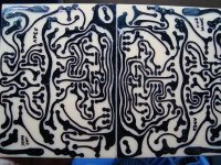
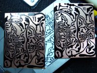
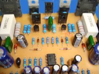
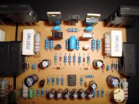
Finally I made it, my PCB....
It's time for shopping...
I'm sorry for my first picture attached, they are reversed.
thx
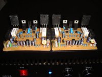
Hand made pcb 🙂
Hand made pcb 🙂
🙂
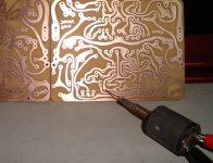
yes it's hand made.
made with DIY tolls too, may someone want to made it like my way?
Perhaps I made it works soon
I want to ask, for testing use 10R/...watt? maybe 5watt or bigger?
Can I change 43k resistor with 47k & 33k with 37k(27k + 10k)?
Thanks you very much Sir
Attachments
🙂
yes it's hand made.
made with DIY tolls too, may someone want to made it like my way?
Perhaps I made it works soon
I want to ask, for testing use 10R/...watt? maybe 5watt or bigger?
Can I change 43k resistor with 47k & 33k with 37k(27k + 10k)?
Thanks you very much Sir
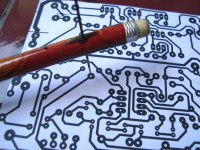
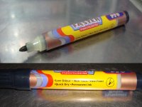
What water-resistan permanent marker you use, and what acid?
For 43k use 33k+10k in series.
Regards
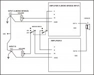
A, B GND IN
good day, can somebody pls tell me what is the purpose of A, and B found with the GND, IN, A, B near the input side of the schematic. thnx
good day, can somebody pls tell me what is the purpose of A, and B found with the GND, IN, A, B near the input side of the schematic. thnx
good day, can somebody pls tell me what is the purpose of A, and B found with the GND, IN, A, B near the input side of the schematic. thnx
A, B pins is for bridge mode
Attachments
I use the big permanent marker, draw with 2 layer for best result.🙂What water-resistan permanent marker you use, and what acid?
For 43k use 33k+10k in series.
Regards
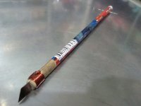
My modified pencil tool is very helping
The acid is water + FeCl3(ferryclorida from e-shop at Denpasar city)
btw I'm just a villager but not so far from the main City (55km)
Now waiting for few more component that my bro will buy tomorrow, we must be patient for best result are we?😀
Okay I will use 33k+10k
Thanks
Regards
Attachments
or like this
An externally hosted image should be here but it was not working when we last tested it.
or like this
An externally hosted image should be here but it was not working when we last tested it.
Professional work

Wah kalah jauh nih saya,...or like this
An externally hosted image should be here but it was not working when we last tested it.
Ayo kang Soer lanjut sampai bberdendang
I'm loose, I just a amateur
Come on Kang Soer make it singing
Finally I made it, my PCB....
It's time for shopping...
I'm sorry for my first picture attached, they are reversed.
thx
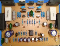
Maybe its should be like this
just wanna fix my mistake
I hope can do it right until this amp works in the right way...🙂
Please help if I go wrong way
Regards
Attachments
Good day guys can somebody pls share me his pcb design and schematic diagram for the protection circuit. Any help would be much appreciated ^_^
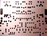
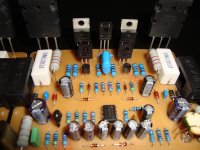
This is new version
This is my new pcb design, change of 43k with 10k + 33k
another one is on page http://www.diyaudio.com/forums/solid-state/164208-500w-pa-amplifier-limiter-176.html
enjoy
Good day guys can somebody pls share me his pcb design and schematic diagram for the protection circuit. Any help would be much appreciated ^_^
This is my new pcb design, change of 43k with 10k + 33k
another one is on page http://www.diyaudio.com/forums/solid-state/164208-500w-pa-amplifier-limiter-176.html
enjoy
Attachments
- Home
- Amplifiers
- Solid State
- 500W PA amplifier with Limiter