hi guys,
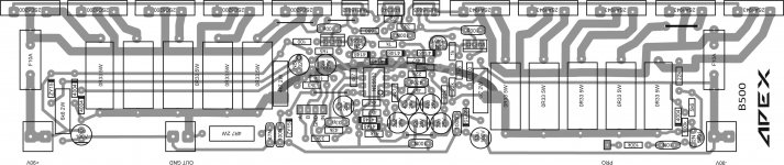
here is the b500 5 pair board.
any mistakes pls inform.
@ narizdigi what software you use to edit this?
@ narizdigi what software you use to edit this?
hi mrching.
i used adobe illustrator.
hi guys,
here is the b500 5 pair board.
any mistakes pls inform.
hi apex sir.
is this 5 pair output pcb correct?
is it power increase or any advantages using 5 pair?
hi apex sir.
is this 5 pair output pcb correct?
is it power increase or any advantages using 5 pair?
Adventages is beter SOA, power increase with higher rail voltage.
Adventages is beter SOA, power increase with higher rail voltage.
hi apex sir,
thanks for the reply,
pls can u share ur h900 v2 pcb layout in pdf.
thanks.
SINGLE PAIR PCB
hi Sir Apex,
hi everyone,
i'm also interesting to make this amplifier
here my pcb design
please help me to check
i'm using ExpressPCB
for beginer like Sir Apex said
thanks
hi Sir Apex,
hi everyone,
i'm also interesting to make this amplifier
here my pcb design
please help me to check
i'm using ExpressPCB
for beginer like Sir Apex said
thanks
Attachments
Last edited:
hi apex sir,
can i use bd241bfi plastic transistor instead bd241c in the protection pcb for thermal.
can i use bd241bfi plastic transistor instead bd241c in the protection pcb for thermal.
hi apex sir,
can i use bd241bfi plastic transistor instead bd241c in the protection pcb for thermal.
Yes
Hi Sir... What's some functions of C6, C7, C8, C9?
With C6, C7 OP amp have feedback from out to inverting input only for AC current, and function of C8, C9 is feedback from amp out only for DC to set offset.
I have some problems with my B500, there is high voltage on pin B driver TR. So, i dont dare connecting to final TR.
I try to measure B to B driver TR, there isn't voltage on it.
I try to measure at pin 1 NE5532, when power turn ON the voltage is increase from 0V to 13Vdc slowly. is it true....????
I have a little question, when normal conditions without input signal,
1. how the voltage at pin 1 NE5532?
2. how the voltage at R15 (1k)?
3. how the voltage at R16 (1k)?
Sorry with my bad english...
Thanks before...
- Home
- Amplifiers
- Solid State
- 500W PA amplifier with Limiter