Member
Joined 2009
Paid Member
Dear MiiB,
It's only intend as a suggestion, nothing harmful at all, and
the sound this way could be pleasant too ..., I'll try both BJT
and MOS version for sure, because each have its specific
qualities, and then only ears will judge ... 🙂
Actually, I did consider some FETS before I settled on the all-BJT output
I have simulated a version with a pair of complementary FETs in parallel with the output BJTs. The idea was to use what Wavebourn calls the 'ideal device' in which a heavily degenerated BJT device is paralleled with a high current FET. It might be the more robust option for low impedance loads.
As a topology, it also looks like Broskie's Class A + C and also like Doug Self's parallel Class G. My heatsink for this project isn't large enough, but perhaps one of you fella's will try it out ?
Actually, I did consider some FETS before I settled on the all-BJT output
I have simulated a version with a pair of complementary FETs in parallel with the output BJTs. The idea was to use what Wavebourn calls the 'ideal device' in which a heavily degenerated BJT device is paralleled with a high current FET. It might be the more robust option for low impedance loads.
🙂 It appears highly interesting especially if more natural sound could be the prize.
 to the good idea . .
 What a joker you are ... 😀
 Ok, I am the first to admit I am a buffoon.
 But one of the "operational" kind.
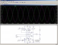
Here is a quick sim of the input section.
Under the test conditions and with a 2K load, the linearity is ~0.3%.
Next is the streamlined version, exactly under the same conditions. R3 and R4 have been slightly tweaked to get exactly the same current in Q5 and Q6, since this is critical for the performance.
Result: the linearity hasn't been degraded, it even has improved somewhat.
The impact of the modification on other aspects is negligible.
Attachments
Member
Joined 2009
Paid Member
I like it Elvee, certainly appears to offer a clear benefit in terms of linearity based on your simulations. The diamond buffer is highly regarded by those that have used it. And you have retained the so-called current feedback (I don't like that term, it's voltage feedback, just happens to have low impedance).
Hi Elvee, I'm realy glad that SSA front-end attracted your attention. Every scientific contribution is always welcome, so is yours as well. My first impression was OMG now he will bombed the design with all that changes mentioned. Also I didn't really exactly dedicated my mind to instructions you've suggested, that is why I said you're probably joking. OK, now when I see the schematics it is clearly obvious of what you're up to. I can say that I don't see it as an improvement although this claim is in direct opposition to THD simulation results. Omiting cascodes in second schematic wouldn't cause such increase of THD, usually their effect is quite the opposite, but as we can see you've also omitted crucial Re's from an input pair and for them, as a gain determination elements, we already know that their values also change harmonic and distortion profile significantly. Not only omitting them, only a little change of their values makes completely different harmonic distortion profile of the amplifier. For the test you can put Re's back to the second schematic and you will see the results. 😉
According to my humble opinion, I would never omit cascodes, cause these are crucial elements of the SSA front-end design, not only improving the bandwidth and lowering power dissipation of the input pair (junction thermal memory distortion) but alowing realy high power supply voltages to the front-end. 🙂
I can only hope your great knowledge will still be present at Gareth's thread, cause I would really like that TGM5 amplifier would become the best sounding small amp here at DIY. Beside that I need something like eight of these channels for my system. 😀
Last edited:
Member
Joined 2009
Paid Member
My plan is to build with the SSA front end. I like the Elvee suggestions, they do make a lot of sense to me, but the 'horse has left the barn' in terms of wholesale changes for the prototype build - I want to hear the design that is currently on the table.
You guys will need a bit of patience, I can't work too fast as things at work are really hectic and I'm away all of next week on a business trip. But now that I have the parts, a design, and some gleaming copper clad board in hand it's a safe bet that progress will resume on my return 😀
You guys will need a bit of patience, I can't work too fast as things at work are really hectic and I'm away all of next week on a business trip. But now that I have the parts, a design, and some gleaming copper clad board in hand it's a safe bet that progress will resume on my return 😀
LV,
You've done it again!! I like it, chiefly because H4 and beyond are now much lower. Harmonic profile is more musical...... and you've eliminated a couple of transistors, never did like cascodes, don't do much from what I can tell.
Hugh
You've done it again!! I like it, chiefly because H4 and beyond are now much lower. Harmonic profile is more musical...... and you've eliminated a couple of transistors, never did like cascodes, don't do much from what I can tell.
Hugh
+1According to my humble opinion, I would never omit cascodes, not only improving the bandwidth and lowering power dissipation of the input pair (junction thermal memory distortion) but alowing realy high power supply voltages to the front-end.
A PM is waiting for you (since days).
Member
Joined 2009
Paid Member
LV,
You've done it again!! I like it, chiefly because H4 and beyond are now much lower. Harmonic profile is more musical...... and you've eliminated a couple of transistors, never did like cascodes, don't do much from what I can tell.
Hugh
Yes, I struggled with the cascodes and nearly jettisoned them first off. But I've never used them myself and with the special dual-transistor chip I'm using for the input their help in reducing power dissipation is much appreciated.
I remember struggling equally with the use of CFP on the input LTP for my TGM2. The simulations showed no benefit to first order (like the cascodes). But boy did they impact the sound. Unfortunately, I didn't like them in the end.
The harmonic profile of the SSA can be easily tweaked to produce lots of even order harmonics, especially H2 - but you knew that already 😉
I've attached the datasheet for the driver/VAS device for your interest.
Attachments
Last edited:
My point was, and always is that cascodes in this case make little difference, in either direction.I can say that I don't see it as an improvement although this claim is in direct opposition to THD simulation results. Omiting cascodes in second schematic wouldn't cause such increase of THD, usually their effect is quite the opposite, but as we can see you've also omitted crucial Re's from an input pair and for them, as a gain determination elements, we already know that their values also change harmonic and distortion profile significantly. Not only omitting them, only a little change of their values makes completely different harmonic distortion profile of the amplifier. For the test you can put Re's back to the second schematic and you will see the results. 😉
I considered the THD change was anecdotic, although higher than expected, but basically an insignificant fluke.
The quiescent current has a much larger impact for instance, which is why I took great care to equalize them.
I neglected the Re's, though, and that's where the fluke is coming from.
From a dynamic perspective, cascoding in this case is neutral, this is shown by the sim, but it is merely a confirmation of what can be inferred by inspection.According to my humble opinion, I would never omit cascodes, cause these are crucial elements of the SSA front-end design, not only improving the bandwidth and lowering power dissipation of the input pair (junction thermal memory distortion) but alowing realy high power supply voltages to the front-end. 🙂
The thermal situation is different, and there could be an impact.
But there are a number of mitigating elements:
-The absolute power level is not very high, and the input transistors always remain in class A.
-Cascoding at the zeners voltage would not eliminate the effect, just reduce it, by a factor of 3 or thereabout. That is not a hugely significant difference, a real improvement would require a factor of ~10, ie a cascode reference voltage of ~4V.
-With this configuration, the main thermal effect would be an increase in the VLF gain, with increased non-linearities coming only as a second order effect.
In short, it would mostly create a very small bass-boost effect.
Cascoding would be much more effective on the output transistors, Q5 and Q6: there, all the conditions are present to make it worthwile: big collector swings, class AB operation with big dissipation swings, and a higher absolute level of power.
Great knowledge.... well,I can only hope your great knowledge will still be present at Gareth's thread, cause I would really like that TGM5 amplifier would become the best sounding small amp here at DIY. Beside that I need something like eight of these channels for my system. 😀
I intervened in this thread because the project still seemed at a relatively early stage, and my contribution could make a useful difference.
I have investigated this family of topologies about 20 years ago, well before the simulation days in fact, and I thus benefit from some prior knowledge on the subject.
I had explored a number of different options then, I'll try to detail the most promising ones.
Attachments

Here is a first alternative, using diodes to bias the transistors.
The diodes are deliberately left unbypassed, so that their non-linearity can partially compensate for that of the B to E of the transistors.
The values are certainly non-optimum, I just threw them at random, but by tweaking the bias current to match the current density of the transistors, a better compensation can be achieved.
The main advantage of this configuration is the good temperature stability: the four diodes compensate for the four transistors.
Attachments
The above idea can be taken further: if two of the diodes are replaced with transistors, the amplifier can be used in an inverting configuration.
This has the potential to improve speed, and eliminate common-mode induced non-linearities.
Here, this potential is not realized because of the output stage.
But when it is combined with a cascoding of the output, it provides a ten-fold increase in bandwidth.
There is a ~3dB peaking at 10MHz, because no attempt has been made to compensate for the increased GBW product.
Attachments
The main advantage of this configuration is the good temperature stability: the four diodes compensate for the four transistors.
I had thought of experimenting with same type transistors as diodes for compensation purposes a few days back on the small Sziklai output SSA. Wouldn't those track better than normal diodes? How can they be best situated to help DC conditions on the original LazyCat front end?
Attachments
But one of the "operational" kind.
Here is a quick sim of the input section.
Under the test conditions and with a 2K load, the linearity is ~0.3%.
Next is the streamlined version, exactly under the same conditions. R3 and R4 have been slightly tweaked to get exactly the same current in Q5 and Q6, since this is critical for the performance.
Result: the linearity hasn't been degraded, it even has improved somewhat.
The impact of the modification on other aspects is negligible.
As another that has experimented and have a 20 year old amp using this topology I have to congratulate you but you shouldnt have shown that circuit 😱 🙁

Dont worry Im just joking. Also have a look at Joachim s interesting variations in the Mpp thread.
I agree with you those cascodes do nothing much for the circuit except they will also change the harmonic spectrum somewhat especially if you add a outputstage to it. As one has a symmetrical circuit even order harmonics would cancel but THD would be very low. The addition of those cascodes brings about lower VCE of input pair and thus higher even but also higher THD and higher orders of harmonics accross the band to the whole circuit due to the early affect as one can gather from your simulations. If you want a amp using a outputstage enclosed in the NFB those cascodes would be required to achieve higher even order harmonic spectrum if that is what is intended or go the route of a seperate folower.
As a next step try cfp as the output and drop the THD to scary low levels, thats the circuit my headphone amp is although I kept JLH DC biasing method on the occasion.
This circuit was first used by JLH back in the sixties as a phono amp and later as headphone amp with minor differences as youll be able to see from here.
The Class-A Amplifier Site - JLH Headphone Amplifiers.
They would track better, but only under "ideal" conditions, for example in a fake differential where one of the transistors is replaced by a diode.I had thought of experimenting with same type transistors as diodes for compensation purposes a few days back on the small Sziklai output SSA. Wouldn't those track better than normal diodes? How can they be best situated to help DC conditions on the original LazyCat front end?
But in Lazycat's front end, there are two stacked diodes, and they are connected to the transistors via the gain resistors.
All this makes a basic, one to one compensation impossible, and having very accurate mirror compensating components is not required.
What is required is to analyze properly the equivalent circuit, and make sure the sum of the transistor's dynamic resistance and that of the emitter network comprising the diodes stays constant under varying signal conditions.
The H2 level caused by each mV peak of dynamic Vbe voltage applied to a naked transistor is approx. 1%.
When an optimum compensation is applied, this is brought down to 0.25%, a 12dB improvement. Not huge, but worthwhile.
Thanks. Can we still use some diodes creatively for harnessing the input pair tempco in LC's front end?
Diamonds are probably a better option, since they have the added advantage of reducing the input current and increasing the impedance. See below.Thanks. Can we still use some diodes creatively for harnessing the input pair tempco in LC's front end?
One could also put diodes as the second member of a fake differential:
Attachments

Exactly the way works my SSA-Crescendo mod.But when it is combined with a cascoding of the output, it provides a ten-fold increase in bandwidth.
With the same results

www.esperado.fr - Le crescendo revisité
Currents are optimized for H distortions. Then CR compensation cap tuned for bandwidth linearity. Then a low pass filter in the input to suppress square waves overshoot and reduce TIM (Signal slew-rate reduced before entering the amp and hf as well).
(It is in French, if somebody can help-me to translate in good English, mine is a miss, i could publish an English version).
One of the beauty of the SSA CR symmetrical topology is you can fine tune the CR caps of each branch to get symmetrical slew-rates on descending and ascending edges.
Agree with LC's "junction thermal memory distortion" argue. And i would add one word about the advantage of the temperature effect in the Cr low impedance resistance, witch compensate in some way the thermal dynamic compression in the charge at high levels ( Dynamic reduction of the loudspeaker efficiency with temperature): do not choose a too much power over-sized serial resistance for the CR.
Last, one of the nice advantages of the cascodes here is to reduce common mode distortion.
Whatever version you'll choose, go on for SSA, the best sounding amp i ever listened to. Thanks so much, Lazy Cat/AndreJ. And thanks to Elvee for his contribution.
Last edited:
Could you elaborate on this, I am not sure I understand exactly what you mean?And i would add one word about the advantage of the temperature effect in the Cr low impedance resistance, witch compensate in some way the thermal dynamic compression in the charge at high levels ( Dynamic reduction of the loudspeaker efficiency with temperature): do not choose a too much power over-sized serial resistance for the CR.
- Status
- Not open for further replies.
- Home
- Amplifiers
- Solid State
- TGM5 - all-BJT Simple Symmetric Amplifier