what kind of amp is this?
sir apex what kind of amplifier is this, can u post the schem and the pcb layout sir..thanks
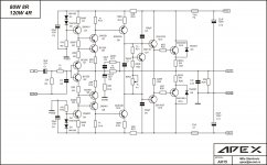
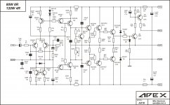
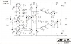
Ultimate Fidelity with more power.
sir apex what kind of amplifier is this, can u post the schem and the pcb layout sir..thanks
Sir Apex, I love your design. But I can't see current source and current miror almost in differential amplifier of your design? Why? Warmth regards..
What is bias current for 2 pairs of output transistors?
I suggest use TEF for 2 pairs or more, and bias 30-50mA per pair.
AX18 TEF
Yes TEF is Triple Emitter Follower output stage like this AX18.
TEF??
Is that Triple Emitter Follower?
Yes TEF is Triple Emitter Follower output stage like this AX18.
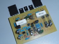
Attachments
30-50ma only ? I run all my amps on atleast 50mA minimum, usually around 70-90mA per pair.
I set 100-200mA, but if someone must ask it's diyer with no expirience and I suggest 30-50mA for first seting, bias can be increase later with lager heatsink.
Emitter Follower outputs require a voltage bias rather than a current bias to maintain the minimum of crossover distortion.
The Emitter resistor is the place to measure the bias voltage.
Most recommend between 15mV and 25mV across this resistor for optimum ClassAB output bias.
The actual current then depends on the value of Re that is fitted.
eg. a 0r1 for Emitter Resistor with 15mVre of bias would pass 150mA of output bias current for each output pair. With a 25mVre bias voltage the current would be 250mA/pr.
If Re=0r47 then the range of bias current would be 32mA to 53mA
But, first you must identify the Vre for optimum distortion performance.
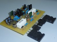
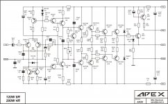
AX20
I suggest use TEF for 2 pairs or more, and bias 30-50mA per pair.
Attachments
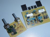
PCB Design
I am very interested in the ax-20 .... how much voltage supply?
Are you will share that pcb design?
Regards
I am very interested in the ax-20 .... how much voltage supply?
Are you will share that pcb design?
Regards

I am very interested in the ax-20 .... how much voltage supply?
Are you will share that pcb design?
Regards
AX20 use +/-60V rail voltage, I won't share pcb designs in future.
Regards
- Home
- Amplifiers
- Solid State
- 100W Ultimate Fidelity Amplifier