thanks lazy cat, did you just mean the green junction dots? if so hows this one?
Better now 😉
So first we'll clear out sch and you'll correct the PCB in accordance to:
- R11, R18 goes out
- C3 should be 4,7 uF so it needs more space around on PCB
- T2 you must change drain and source pin !
- please provide two 1N4007 in series diodes, parallel to C4
- please add one extra 1 uF cap parallel to C4
After sch + PCB correction I can check. 🙂
Last edited:
... can i substitute the NJL outputs for MJL , is there a difference ...?
You can, but than you will need linear Vbe multiplier (one TO-126 BJT, one diode, one multiturn trimmer, two resistors) instead of four thermal-track diodes. No big deal. 😉
Hello LC,
Can we do the calculations for the necessary values with an PSU output of 35volt, i already have 1000va trans @ 25v..
regards,
Can we do the calculations for the necessary values with an PSU output of 35volt, i already have 1000va trans @ 25v..
regards,
Hello LC,
Can we do the calculations for the necessary values with an PSU output of 35volt, i already have 1000va trans @ 25v..
regards,
By the +/-35V supply voltage to an output stage you will get maximally 300Wrms/1ohm, that means 25Vp and 25Ap, so you will need 4 pairs of the output BJTs and a lot of cap filtration in PSU. 😉
Last edited:
I have currently 200K/ uf/ch ... let me know if more is necessary ...🙂
4 prs sound small for such a load, as do the power output from an 35volt PSU, can i ask how you are arriving at the 25 volt out from 35 volt supply...?
4 prs sound small for such a load, as do the power output from an 35volt PSU, can i ask how you are arriving at the 25 volt out from 35 volt supply...?
Last edited:
I have currently 200K/ uf/ch ... let me know if more is necessary ...🙂
4 prs sound small for such a load, as do the power output for an 35volt PSU, can i ask how are you arriving at the 25 volt out from 35 volt supply...?
100 mF per rail? It is OK
Well realistically is like that. 35V rails voltage potential (idle) -10V (rail drop + Vcesat) at 1 ohm load and you will get 25Vp and 25Ap unclipped level at amp's output and that is exactly 312,5 Wrms on 1 ohm. Four pairs BJT-s like 2SA1987/2SC5359 can handle that peak values without problems. 😉
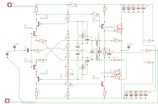
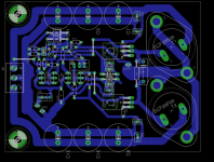
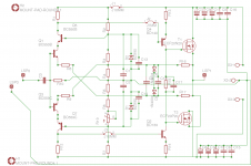

One more thing regarding PCB:
- Q1 and Q3 have to be face to face glued together. This is mandatory.
- Q2, Q4 each should have small heatsink, also mandatory.
- T1, T2 probably there will be Al L-profile fixed to heatsink? Provide good thermall contacts ...
That's it. Bye 😉
- Q1 and Q3 have to be face to face glued together. This is mandatory.
- Q2, Q4 each should have small heatsink, also mandatory.
- T1, T2 probably there will be Al L-profile fixed to heatsink? Provide good thermall contacts ...
That's it. Bye 😉
100 mF per rail? It is OK
Well realistically is like that. 35V rails voltage potential (idle) -10V (rail drop + Vcesat) at 1 ohm load and you will get 25Vp and 25Ap unclipped level at amp's output and that is exactly 312,5 Wrms on 1 ohm. Four pairs BJT-s like 2SA1987/2SC5359 can handle that peak values without problems. 😉
Thanks LC,
awaiting the values necessary to hear an SSA at power .....
 🙂
🙂Balanced I/P with proposed Values
Hello Lazy Cat,
Please provide also above mentioned version for me, equipped with the
balanced input would be excellent and an option to switch it to a SE input.
I have the 1000W-35V AC transformers waiting to be used exactly for the proposed amp.
I wonder to use six pairs of the 2STC5949 + 2STA2121 OP transistors.
Thank You in advance.
a.wayne no problem 😉
For the power 800Wrms/1ohm, peak output voltage will be 40Vp, and peak output current 40Ap. Output transistors behave normally up to Ic=6-7Ap so you would need six pairs of the outputs, +/-50V supply voltage for the output stage and +/-60V for the SSA front-end. Some components values have to be recalculated and I can prepare this especially for your specific case till tomorrow. 🙂
Hello Lazy Cat,
Please provide also above mentioned version for me, equipped with the
balanced input would be excellent and an option to switch it to a SE input.
I have the 1000W-35V AC transformers waiting to be used exactly for the proposed amp.
I wonder to use six pairs of the 2STC5949 + 2STA2121 OP transistors.
Thank You in advance.
thank you Lazy Cat, yes ill glue the faces together on the input trans and yes a drilled 5mm L bracket for the output fets, thank you so much for the help, steve.
thank you Lazy Cat, yes ill glue the faces together on the input trans and yes a drilled 5mm L bracket for the output fets, thank you so much for the help, steve.
Your PCB does not correspond to that request. 🙄
Q1 and Q3 have to be face together, not like it is now, so please rearrange the input section completely. 😉
20Apk output capability is equivalent to 200W into 1r0 resistor.Hello LC... goal is 600-800 watts/ch into 1 ohm or 20 amps capability per channel.
20Aac (28Apk) is still way too low a target for driving 1ohm speaker combinations.
50Apk is a more reasonable (minimum) target for driving 1ohm or 2ohms speaker combinations.
Last edited:
20Apk output capability is equivalent to 200W into 1r0 resistor.
20Aac (28Apk) is still way too low a target for driving 1ohm speaker combinations.
50Apk is a more reasonable (minimum) target for driving 1ohm or 2ohms speaker combinations.
He might want a 200 or 800 watt amp.
20Apk output capability is equivalent to 200W into 1r0 resistor.
20Aac (28Apk) is still way too low a target for driving 1ohm speaker combinations.
50Apk is a more reasonable (minimum) target for driving 1ohm or 2ohms speaker combinations.
800 watts is what i would end up with if a true voltage source, from practical experience in use i rarely exceed 10amps on the outputs/ch , hence the 20amp/ch number.. At 1 ohm you are effectively making a current speaker not voltage.
20 amps capability/ch with full stability, low distortion and good sonics is the goal ...
He might want a 200 or 800 watt amp.
Yes i sometimes exceed 10 amps on dynamic passages, 20 amps output capability per channel should get me there...
20Apk output capability sounds more like a nice target for driving 8ohms speaker loads. Certainly not suitable for driving 1ohm or 2ohm speaker loads.
In theory yes , in practical use no. I have never blown an15amp output fuse, 10 amps yes , 15 amps no! 200-400watts rms @1ohm will suffice, plays dynamic enuff with that..
PS: Very few can handle such , even the big ones who claim 50-70 amps capability /ch.. i know , i tried them .
PS: Very few can handle such , even the big ones who claim 50-70 amps capability /ch.. i know , i tried them .
I accidentally max power tested a power amp with the wrong rail fuses in place.
The load was seeing >400W and yet the tiny test mode fuses in the supply rails did not blow. I don't remember the actual numbers but I posted about 4 or 5years ago.
From there I came up with my advice on sizing the rail fuses for all amplifier powers and impedances.
Quasi came up with exactly the same method but lowered the fuse rating by a factor of sqrt(2).
On that basis the output fuse should be approximately twice the rail fuse ratings since the rail fuses are on 50% duty factor and the output fuse is on 100% duty factor.
If you blow a 10A output fuse you have done something really silly. If you blow a 20A output fuse you are worse than silly, you need a "God" looking after you. "God" = or any other supreme being to protect you.
- Status
- Not open for further replies.
- Home
- Amplifiers
- Solid State
- Simple Symetrical Amplifier