Member
Joined 2009
Paid Member
I am only a temporary vice-president of the DX-corporation and am making my contributions under direction of the CEO (= uncle Charlie Executive Officer !) you have seen his 4-barrel shotgun !
I do like open discussion of ideas also (see my hybrid thread for Cellini-2), but this forum is big enough for all approaches to design of hybrids.
Personally, I find it a challenge to have a hybrid thread when we don't have a forum for this - neither Tubes forum or SS forum is the ideal place. Perhaps if there is enough interest the God of the Forum will give rise to a new 'Hybrid Amplifiers' forum.
Last edited:
One Approach......
Carlos, Gareth,
This would bring tube color to the sound because the first tube is not in the feedback loop.
Consequently, the gain of the closed loop section would need to be small; alternatively, you could reduce the gain of the first tube section by simply taking the output from a tapping on the 10K resistor.
BTW, I suspect the 10uF decoupler on the 3K6 resistor of the pnp device should be taken to the positive rail, not to ground. My mistake...
This is not refined, of course, more simulation required, but it's an idea to consider.
Cheers,
Hugh
Attachments

Thank you very much Hugh.
We gonna try several options....your idea will be tested, will be assembled and evaluated.
We will not publish our decisions about... we will collect informs from others, suggestion collected by Gareth in this thread or in another one he may open (much better this way) and we gonna decide latter the circuit we gonna use.
So, we gonna capture ideas in other thread... some of them we will discuss internally and will test.... and we may use or not...the final schematic will be keep in secret till the release date.... it will be the result of our thoughts, also the result of suggestions and circuits tested and the ones that suggested sub circuits and ideas will be nominated.
Thank you Hugh.... much appreciated...you know i do respect you a lot...you are one of my important teachers.
regards,
Carlos
Carlos,
It's a genuine pleasure, I hope this is useful to you both and brings a tubey sound, which I think is probably the whole idea of a hybrid.
Hugh
It's a genuine pleasure, I hope this is useful to you both and brings a tubey sound, which I think is probably the whole idea of a hybrid.
Hugh
Member
Joined 2009
Paid Member
brings a tubey soundHi Hugh,
I believe this would be easier to achieve without making a hybrid, just put a single tube pre- in front of a regular unchanged DX amplifier...
tubes and transistors make strange bedfellows don't they 😀
Last edited:
We gonna build and check several options.
then we gonna see the result...thank you very much dear Hugh.
Your circuit will be assembled...also the single tube will be tested, the differential and VAS tubes too...i do like to do these things.... sadly i will not be able to make two and compare...will be one by one... assembling and dismounting because of small tube quantity will be available.
But even this way i do think i have a chance to perceive the one will result better... well... i have no other way.
When we compare A with B amplifiers...and C with D..... say... two tests..each test with two amplifiers, the traditional A to B comparison...them we may have A and C as winners.... then we have to compare A and C..... having too many ideas the comparison becomes laborious...so...i will have to limit options as i cannot assemble same time A, B, C, D and E
We have already four options...i do think i will select 5 and will try them based into simulations (selection)... despite simulations says nothing about the sonic result...but this is the tool i have...also reviews about.
Tubes usually goes to 0.1% THD..... 0.06% was the minimum i could have..and the Dx output..or EF amplifiers output without NFB goes to the same value..and this sometimes add one to the other (different harmonics)...this is a problem to advertise as people believe in numbers (majority)
regards,
Carlos
Hugh...i have got your message
You have tried several options and you gave us clues...as usual...people do not perceive your clues because distrust...this does not happens related me dear Hugh.
I have received the message...that diode...the positive rail and the input tube.... reduce gain and use the tube as complementary preamplifier.
Be out of the feedback loop.
Thank you..this gonna be tested in the first place.
regards,
Carlos
Well dear Bigun.... i discovered you already have a Hybrid with tubes thread
So, this one we are running does not make any sense...this was already researched.
http://www.diyaudio.com/forums/tubes-valves/174889-cellini-2-hybrid.html
regards,
Carlos
So, this one we are running does not make any sense...this was already researched.
http://www.diyaudio.com/forums/tubes-valves/174889-cellini-2-hybrid.html
regards,
Carlos
Member
Joined 2009
Paid Member
The first batch of russian tubes have arrived ! little cardboard box waiting for me when I got home today. A little clutch of 6N23Ps.
Silly me didn't order sockets, I was holding off to see if we wanted some other kind of tubes and I think possibly we do. I need to look around to see if I have any sockets but will order some shortly anyway.
Silly me didn't order sockets, I was holding off to see if we wanted some other kind of tubes and I think possibly we do. I need to look around to see if I have any sockets but will order some shortly anyway.
Member
Joined 2009
Paid Member
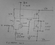
Here is my latest schematic. It is simpler than the first one, using only one triode. It is inspired by Super Triode connection, as invented by Shinichi Kamijo
see: The Super Triode Connection Ver.1
What I am proposing is not strictly a super triode connection, it is a hybrid. I thought that a triode in the input preamp-style might seem like ground well-trodden but there are two inputs to an amplifier - inverting input and non-inverting input. The inverting input for DX amplifier is used for the feedback signal. So I thought about using a triode as the input stage for the inverting input.
The attached sketch gives the idea. It's now an asymmetrical hybrid long tailed pair. Unlike the standard DX amplifier the LTP is inverted to allow use of NPN transistor(s) as it needs to match up with the triode which as you know is only available as n-type. The VAS is now a PNP type. Everything else remains unchanged.
Only one triode per channel means one glass bottle is sufficient for a stereo amp and it would be fun to mount it where it can be seen. The 6N23Pi is a good tube and has an electrostatic screen between the triodes inside the glass to ensure good electrical channel separation. The 6N1P is another choice, it prefers higher voltage and current. The 6N2P provides more gain. There are more tubes in this family as well as European and US equivalents (the E88CC comes in some expensive flavours) and as they share a common pin-out you will be free to try them all ! Just be careful to ensure you plan for enough heater current as some tubes need more than others.
So it is a familiar topology for anybody who has looked at the DX amplifier and similar amplifiers.
Another benefit of placing the triode into inverting input of the LTP is that the output from LTP is now still from the collector of the non-inverting input transistor which of course is not at a high voltage as was the case in the first schematic I posted. This means that the Taylor Follower type PNP transistor is not needed. The triode will still perform it's best if given a higher power supply voltage than the regular amplifier rails but it's now a single voltage low current supply. The triode does not face a particularly difficult load in this position and can be a high quality medium mu triode as shown.
The usual consequence of an asymmetrical LTP is dc offset at the output. In this case it is adjustable to zero by changing the current flow through the LTP tail - as is usually the case when no current mirrors are employed (and none are recommended). The tube needs more current than the input transistor anyway.
Since the tube presents a high impedance connection for the feedback network, and the dc offset is no longer dependent on the base leakage current of the feedback transistor (as I replaced it with a triode) then the impedance of the feedback network could be reduced or increased compared with a regular DX. Lower resistor values means lower noise. But lower resistors means higher current and the need for a larger shunt capacitor in the feedback network. Pick your poison.
I have simulated the circuit in LTSpice using tube models from Duncan Amps. The harmonic profile shows the anticipated H2, then H3 and then much smaller harmonics after that. I will try to post the results after the weekend.
p.s. this design was rejected by DX corporation so it can be released, it is no longer a secret 😉 so I offer it for anyone who's interested - and quite likely somebody will know where this design has been done before
Attachments
Last edited:
Member
Joined 2009
Paid Member
I should add that tubes have the disadvantage at start up that they are cold and don't conduct - meaning the nfb network is dead for awhile and that means dc offset at output will require some handling - such as relay delay turn-on of speakers.
The good thing is that this circuit avoids the B+ coming into contact with any of the BJTs - as slowly warming tubes in common cathode configuration with outputs from their anode have B+ on said anode at power up before current flow through the tube pulls it down - which may not be kind to where the anode is connected - sometimes a reverse bias e-b further on resulting in dead transistors. Only other option with common cathode is to use capacitor coupling, but who wants capacitors within the global negative feedback loop ?
The good thing is that this circuit avoids the B+ coming into contact with any of the BJTs - as slowly warming tubes in common cathode configuration with outputs from their anode have B+ on said anode at power up before current flow through the tube pulls it down - which may not be kind to where the anode is connected - sometimes a reverse bias e-b further on resulting in dead transistors. Only other option with common cathode is to use capacitor coupling, but who wants capacitors within the global negative feedback loop ?
Bigun,
The cold start issue with tubes may require a relay to short tube grid to ground for the first twelve seconds. No big deal; at warm up, sensed by a servo (an optocoupler is fine) operating off the cathode resistor, relay is deactivated and normal fb commences.
Having built something very like this once, I can tell you it will have good image depth but a rounded presentation. If you can put the tube outside the fb loop - and there is a way of course - it will be more 'tubey', whatever that might be.
Hugh
Hi Bigun,Here is my latest schematic. It is simpler than the first one, using only one triode....
why not triode as the input dedice instead of the transistor? DC conditions/offset at he start? Or STC must be topology?
VAS transistor tends to introduce big memory distortions, maybe cascode it?
Please send distortion distribution plot.
Member
Joined 2009
Paid Member
If you can put the tube outside the fb loop - and there is a way of course - it will be more 'tubey', whatever that might be.Hugh
If you think about how LTP works, it is already outside of the fb loop - it defines the transfer curve of the LTP and therefore the fb loop can not 'correct' it's non-linearity.
I could be wrong ... but I believe the DX corporation was not looking for a tubey sound per se (whatever that might be), it was looking to retain the qualities of the DX amplifier but in a hybrid format to try out the effect of adding a new 'spice' into the recipe 🙂
Hi Bigun,
why not triode as the input dedice instead of the transistor? DC conditions/offset at he start? Or STC must be topology?
you can do that, it's equally valid place to put a triode. can you try it ?
it creates complications due to the high voltage on the anode being the take-off point for the VAS (see the first schematic I posted).
VAS transistor tends to introduce big memory distortions, maybe cascode it?
according to my family I often get memory distortions 😀
I read a website all about memory distortions, the gentlemen did a lot of simulations and experiments to show the effect and to propose cures. It looked interesting. Then I realized that all the improvements he made, such as CFP and Cascodes and other methods, they were capable of changing the performance of the amplifier by a very large amount even if there was NO memory distortion. so how do you separate out the effect ? to me it remains un-proven and I'd rather not add all those devices. perhaps a more controlled experiment could be devised, using non-feedback amplifier and simple topology - what do you think ?
what do you think ?
you might be right, maybe this way of measuring memdist is not too correct, because other parameters are much improved,
but I saw many experiments in which using cfp + cascoding at the input led to improvements in the sound,
until now I thought that was because of lowering memdist...
Member
Joined 2009
Paid Member
I used CFP in my LTP before, it was my TGM2 amplifier thread. It definitely changes the sound compared with simple LTP (from TGM1 for example). The amplifier was a completely different animal. But the CFP brings a whole bunch of things to the table that are quite significant and in my opinion likely swamp the effects of memdist.
The CFP input is much more linear because of the inherently high local feedback loop. It forces better matching between the two sides of the LTP. The result of these two things are that the LTP, as an error amplifier, is more accurate. It changed both the bass and the high's.
And on the topic of hybrids, my very first thread on the topic of hybrids was a CFP. In that thread I proposed a MOSFET is added to a triode in a CFP topology to make a compound device out of triode + solid state. The idea is that the triode is the 'master' device and it's character is impressed on the sound, whereas the FET is the 'slave' device and it's job is to provide current drive. I haven't built it yet - maybe something I will try out.
And on the topic of hybrids, my very first thread on the topic of hybrids was a CFP. In that thread I proposed a MOSFET is added to a triode in a CFP topology to make a compound device out of triode + solid state. The idea is that the triode is the 'master' device and it's character is impressed on the sound, whereas the FET is the 'slave' device and it's job is to provide current drive. I haven't built it yet - maybe something I will try out.

my simply (mis)understanding:
tubes do not suffer from he memdist,
they are still hot (after the heater is heated),😀
transistor's junction remembers for a while higher current peaks
untill is forced to working in class A
and is all the time hot - higher current peaks do not heat it more,
the same thing is is when working with CFP with constant current/voltage(?)/power on them.
this is the secret why class A sounds better

- Home
- Amplifiers
- Solid State
- Dx hybrid amplifier will be produced soon