Remote sensing places it essentially in touch. Since we don't know the ins & outs of such difficult designs, just try it out and judge if you get better or worse results to your sonics. That's the goal after all, and its the simplest test. Those regs can be used for so many circuits, that will not remain unusable for long anyway. Will be nice to let us know what happened.
sense works to bring it closer for voltage stability performance, i realize that, but i wondered about how distance might effect dynamic/transient performance when talking about such high speeds. but i suppose thats where the local caps come in. for sure i'll let you know how it goes. audible performance is all I have, luckily its the most important, but i dont have the gear to measure performance at this level.
wont be for a couple of weeks, because my first package got ermmmm, lost. i wont say any more to protect the over worked and over tired 😀 he knows who he is hehe and given Tea's track record and handling of the problem it is perfectly acceptable/understandable. you know what they say, its not just about how infrequent problems are, but about how they are handled when they inevitably do every now and then, that makes the difference between people you like to deal with and those you dont
wont be for a couple of weeks, because my first package got ermmmm, lost. i wont say any more to protect the over worked and over tired 😀 he knows who he is hehe and given Tea's track record and handling of the problem it is perfectly acceptable/understandable. you know what they say, its not just about how infrequent problems are, but about how they are handled when they inevitably do every now and then, that makes the difference between people you like to deal with and those you dont
Last edited:
The high clock speeds are produced inside the clock and are routed on buses. The clock only asks for DC to operate from. Side effects of the clock coupling on rails and ground is we seek not to exaggerate their coupling ability by bad impedance in the very high range. There the decoupling and layout are the main strategies. Remote sensing preserves the reg's Zo, hence its dynamic performance over the needed wires. Its good to have for all main parameters. We don't ask the DC source give bursts of power in the MHz but linear power at 0Hz... There was a member with an oven XO and DAC on P2P 1.2R. He was chuffed with the sound upgrade over what chip regs his system was using before. When he poked with his wide bandwidth DSO around, he was surprised to see 98MHz clock multiple on rails, gnd, associated digital stages on PCB etc. He did decouple better, lowered it, but did not eliminate. So he went a step back and re attached his old regs for a check. Same stuff! The gremlins were there before, he just hadn't looked before. The probe can pick from its ground crock clip inductance on clock field radiation even. He uses 1.2R again and started reading more Robert A. Pease on measurements and interference, plus general digital layout stuff, were his last words from then.🙂
yeah, what i meant was, as the clock is running so fast the slew rate and ripple created has got to be pretty fast/large yeah? i didnt mean that the power had to be modulated at that speed, but i guess it kinda does when power demands change along with it, not in a direct way though, thus dynamic performance.
but i take your meaning that this is the clocks problem internally and since sabre is basically async in my build the clock speed probably doesnt change, so as long as the power is kept up to it theres no problem on that side anyway, but its effects as you say will be felt on the rails, but thats probably beyond the control of whatever is powering it nomatter what it is. a funny old world at those speeds for sure, beyond my understanding, since its basically RF design.
on my particular model there appears to be 2 small caps across the rails just under the external can, dont know if they are part of their mechanism to make sure the external supply is of a standard that will work, or whether they are part of the clocks own power supply.
Last edited:
Digital circuits should work non dirty on any decent power, be it an LM317 or 7805 even I believe. They should not rely on anything beyond their own layout, decoupling, and shielding for behaving well in the interference department. Then they can benefit on better power delivery for DC. If they are all over the place, even a cm of pcb track has enough inductance to have no low impedance at 100MHz. Nobody would expect all same band cellphones being the same for interference for instance just because they all run on alike battery. Some are better engineered and some are worse.
@qusp
you are trying to solve equation on the wrong side. No regulators will work at 100 MHz, proper layout and local decoupling caps are your best friend, as Salas told you.
Even if they do work @100 MHz, for digital clocks HF hash is not that important, it can be easy removed with local decoupling caps.
For audio digital clocks (quartz crystal based) LF noise (1/f noise) is much more important. You need good performing regulator at 0Hz...10Hz...100Hz, not good performing regulator @100 MHz.
Last edited:
That is why I recommend 220uF electrolytic reference voltage filtering for feeding clocks and low MC phonos in the guide.😉
@qusp
you are trying to solve equation on the wrong side. No regulators will work at 100 MHz, proper layout and local decoupling caps are your best friend, as Salas told you.
Even if they do work @100 MHz, for digital clocks HF hash is not that important, it can be easy removed with local decoupling caps.
For audio digital clocks (quartz crystal based) LF noise (1/f noise) is much more important. You need good performing regulator at 0Hz...10Hz...100Hz, not good performing regulator @100 MHz.
not trying to solve any problem, its about as under control as its going to get, i'm trying to understand the limitations of the regulator and where the line of responsibility between capacitor and regulator is. not just for this project, but a portable one with a portable buffalo 2 plus extras and a diy regulator/control board.
I'm also interested in soon removing the clock at this end and using an even higher grade clock (probably an OCXO) as a master clock to feed the dac and usb->i2s. i just find it interesting and thanks both of you for you time.
Salas: is the recomendation for the 220uf electro based on dielectric performance, or simply size?
ahm... 100MHz? Consider yourself lucky to get low and flat output Z around 20kHz AND a stable regulator! Not that easy.
i think you took my wording of 'limitation of the regulator' the wrong way, everything has limitations, just trying to find where they are so i can put effort and funds towards where they will make the most difference. has no bearing on the pretty much unanimous approval of this great design. i'll certainly continue to use it, whether i use it in this position or not
decoupling rules over all it seems, even the fastest high end chip regulator and chip/mosfet follower designs for CPU konk out and leave it up to decoupling at some point.
decoupling rules over all it seems, even the fastest high end chip regulator and chip/mosfet follower designs for CPU konk out and leave it up to decoupling at some point.
Last edited:
Salas: is the recomendation for the 220uf electro based on dielectric performance, or simply size?
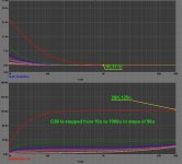
Size. Gets the output noise down by filtering the reference locally more, leaving less noise to be amplified internally. Dielectric is mediocre. But you don't care about that for a clock, you want best 1/f noise on the noise graph's left. See the noise stepping with capacitor values noise analysis. Comes from a third party and my LT Spice one followed it nicely. I listened to a double mono BIB @ 35V with separate 100VA M6 EI Tx for MC Simplistic phono, where I recommended 47uF FC 63V//0.022uF FT1 Teflon underneath for C101,102,301,302 and it was open, very good balance and detail. There it matters for the whole audio spectrum. That circuit has very limited PSRR and high gain though. If it was with OPAMPS or had current sources as loads 10uF MKP would suffice. No oscillation frequency could be found on 20cm twisted sense and force cables both with a 100MHz DSO and a a 50MHz Philips CRO, on actual load mode @ 200mA set for each channel. 1,8V over R101,301.
Attachments
Try using a tube for driver and shunt device. You'll get bandwidth alright.
thats a very interesting idea
Size. Gets the output noise down by filtering the reference locally more, leaving less noise to be amplified internally. Dielectric is mediocre. But you don't care about that for a clock, you want best 1/f noise on the noise graph's left. See the noise stepping with capacitor values noise analysis. Comes from a third party and my LT Spice one followed it nicely. I listened to a double mono BIB @ 35V with separate 100VA M6 EI Tx for MC Simplistic phono, where I recommended 47uF FC 63V//0.022uF FT1 Teflon underneath for C101,102,301,302 and it was open, very good balance and detail. There it matters for the whole audio spectrum. That circuit has very limited PSRR and high gain though. If it was with OPAMPS or had current sources as loads 10uF MKP would suffice. No oscillation frequency could be found on 20cm twisted sense and force cables both with a 100MHz DSO and a a 50MHz Philips CRO, on actual load mode @ 200mA set for each channel. 1,8V over R101,301.
thanks for that Salas, very interesting chart indeed. i think I just found my first victim for the new CDE 944U 220uf DC link polypropylene I ordered earlier this week. I bought it to just put after the batteries in place of the regulator, but i'll try it here too. i want to test them out and grab for my SS circlotron power supply..
huge though at 84mm diameter and 65 tall
An externally hosted image should be here but it was not working when we last tested it.
i was actually going to ask you about paralleling a teflon or perhaps just a 0.1uf smd pps film under the board directly across the leads in that position, i wondered if there might be inductance/resonance between the 2 caps that would make it counterproductive?
pity the only physically small teflons i know of are the relcaps, a bit pricey to sprinkle liberally over a regulator. you can get CDE tiny teflon RF caps in a really little smd metal can, but only up to 5pf, above that they are mica
decoupling rules over all it seems, even the fastest high end chip regulator and chip/mosfet follower designs for CPU konk out and leave it up to decoupling at some point.
Have any Zo graphs from such? The BJT 1.1 is predicted 100kHz flat Zo and its designed with linear audio in mind. Its surely stable, I have one on my bench.
thanks for that Salas, very interesting chart indeed. i think I just found my first victim for the new 220uf DC link polypropylene I ordered earlier this week. I bought it to just put after the batteries in place of the regulator, but i'll try it here too. i want to test them out and grab for my SS circlotron power supply..
huge though at 84mm diameter and 65 tall
i was actually going to ask you about paralleling a teflon or perhaps just a 0.1uf smd pps film under the board directly across the leads in that position, i wondered if there might be inductance/resonance between the 2 caps that would make it counterproductive?
pity the only physically small teflons i know of are the relcaps, a bit pricey to sprinkle liberally over a regulator. you can get CDE tiny teflon RF caps in a really little smd metal can, but only up to 5pf, above that they are mica
Come on! That's larger than the reg! The cables to position are going to add many nH to resonate. Use a 100uF PanaFC on C101 and put a Russian FT1 teflon 22nF for C102. Cheap. Fits directly.
haha, i'm not seriously thinking of leaving it there, just having a bit of fun with a new toy. with the battery i can just place it directly across the terminals with the solder taps screwed into the terminals and the resulting unit should leave the leads at roughly the same height as my dac + D1 and heatsink stack. so connections should be very short; but i'll keep the recommendation in mind, i always thought those russian teflons were huge, never had one here in the flesh.
wrt the graphs, i was just agreeing with your and ikoflexer's comments that layout and decoupling rule at very high speeds. The lt1575 datasheet i linked on the previous page (plus the lt1764A datasheet if you look at that, the lt datasheets are very thorough) that up in the clock speed domain you really have to leave it up to layout and decoupling to do their job. the lt1764A only covers frequency vs transient response, ripple rejection vs frequency (about 25db at 100khz and 19db at 1mhz) noise vs frequency (30uV over 10hz->100khz with 3A load) etc etc, but the lt1575 system from what i gather is their fastest transient response offering, but they dont give a lot of specific info with noise or output z, as it depends on what mosfet you use it with.
wrt the graphs, i was just agreeing with your and ikoflexer's comments that layout and decoupling rule at very high speeds. The lt1575 datasheet i linked on the previous page (plus the lt1764A datasheet if you look at that, the lt datasheets are very thorough) that up in the clock speed domain you really have to leave it up to layout and decoupling to do their job. the lt1764A only covers frequency vs transient response, ripple rejection vs frequency (about 25db at 100khz and 19db at 1mhz) noise vs frequency (30uV over 10hz->100khz with 3A load) etc etc, but the lt1575 system from what i gather is their fastest transient response offering, but they dont give a lot of specific info with noise or output z, as it depends on what mosfet you use it with.
Last edited:
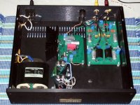
From its OLG graph and 220uF electrolytic across output don't expect miracles of extension. Although very good. Its just settling rapidly for high current step. Which is important in computers. FT1 22nF are those 4 silver ones on the right board, and the one behind the ERO MKC on the 1.2R reg left hand smaller board, to get a size idea.
Attachments
.jpg)
??? I havent bought the lt1575, just started thinking about it the other day while searching the site and thought it looked like an interesting idea. i wouldnt put a 220uf cap on the output of a fast reg like that, might even damage it. I'm not using a regulator with the film cap, the lt regs i'm using and the ones i gave numbers for (LT1764A), i'm using in a portable sabre dac unit for the clock and main dac supply with minimal output caps (10uf smd panasonic solid polymer and 10nf np0).
the big film cap is just going with the battery and nothing else with the clock in the home unit, the battery is the perfect voltage for the clock, doesnt need a regulator, but i have been using the batteries to power the stock AD797 based regulator in the VOSC and AVCC positions, which probably has extremely good speed if i know that chip
i'm trying all sorts of combinations with it and the analogue supplies for a 32bit/384khz usb->i2s i'm playing with, and i want to eventually power the dac and usb-i2s joint master clock (sabre slaved to that too) with one of these. i'll be using the BiB for the AVCC L/R and reference positions, but the clock is up in the air, thus this query. probably also using the mosfet BiB for powering the D1 IV stage at +/-45v and about 150-200ma, but that depends on whether it fits, or whether the chassis floor is enough sink, as i dont have enough room for any more big sinks
anyway we've spent enough time and space talking about this in the build thread. ill grab some of those teflons though, so thanks for the heads up/enlightenment regarding how small they are. i'll be back when my boards arrive and i've built them up with some pics
All right, good luck configuring, let us know what combination played best when time comes. I see many with powering digital stuff in mind here, they are surely interested I guess. Me I will just throw one acronym for the time being bcs I got jealous with so many digital acronyms. V.I.N.Y.L.😀
hehe yeah sorry for all the acronyms , for interest sake, AVCC L/R are the 2 pins for the sabre dacs analogue output stage left and right channels and is 3v3 @ 30ma, VDD L/R is the supply for the dacs analogue reference and are 1.2v @ 2 x15ma and VOSC is the clock @ 3v3 and 10ma in its current form, for a 100mhz clock. the D1 IV is just that, the IV stage from the Pass D1, but modified and streamlined by opc for the sabre, we run it at higher voltage too for higher gm, with different mosfets and a massive heatsink to get rid of the 50W. i consider all of these analogue supplies, sure its a digital unit, but these are not digital supplies, so the quality of them in my experience is actually quite important for best sound.
also, didnt mean to cut you short, i do appreciate the help and answering my questions, i just became conscious of the amount of space my query was taking up in the build thread before i even have the pcbs in my hands.
vinyl? meh hehe digital all the way here, although i do like my Djs to use it. it definitely has character, but its just not my thing
Last edited:
- Home
- Amplifiers
- Power Supplies
- SSLV1.1 builds & fairy tales