Hi all, I'm just new to the forums here 🙂
I was considering building an amp for a nice set of speakers which I already have. A chip based amp seems like the easiest way but my speakers are 16 Ohm which appears to make things a bit more difficult. A common chip people here seem to use is the LM3875 which has a brilliant datasheet, unfortunately it contains no information about 16Ohm applications.
I read about bridging two chips together and wikipedia says an amp rated '100W into 4Ohms will appear as 200W into 8Ohms" so in the case of the LM3875 56W 8R -> 112W 16R which would be great. But have you seen this done before? I couldn't find much about how to do it. I'd like to take as much guess work out of it as possible and be sure about what i'm doing by keeping things reasonably simple, though I am good with electronics in general, just don't know much about audio.
Perhaps I need a chip that already supports bridging (like the ST TDA7296) or a different chip which is already suited to 16Ohm loads?
Also, how much might a project like this cost? i'll need L/R amps rated to about 80W per channel, but not sure about how much 'quality' i want.
I'll stop there now! It is already an essay but i'm sure i'll come up with more questions, cheers guys 🙂
16 ohms is easier than 8 because it takes less current. So bridge your amp and whatever the claimed power into 8 ohms is, divide it by 2 (because you have 16 ohm loads) and you'll have your answer and the amp will run cooler than with 8 ohms. Don't fret over this.
G²
G²
So the new power rating would be 56x2 (because of the two amps) divided by 2 (because of 16Ohms) bringing me back to a maximum power of 56W per channel?16 ohms is easier than 8 because it takes less current. So bridge your amp and whatever the claimed power into 8 ohms is, divide it by 2 (because you have 16 ohm loads) and you'll have your answer and the amp will run cooler than with 8 ohms. Don't fret over this.
G²
Oh and I found a bridged example here. Are the LM38xx the chips of choice then? what about the ST TDA range?
Oh yea and as for power supplies, is there any preference between + - 25V and just +25V supplies? (single supply gives a more complicated circuit but would remove the need for two supplies) And is it ok to get -v by connecting the ground and +v rails together on the two supplies.
So the new power rating would be 56x2 (because of the two amps) divided by 2 (because of 16Ohms) bringing me back to a maximum power of 56W per channel?
No. Bridging the amp doubles the Voltage and current into the load so the power goes up by 4 and your power goes to 220 Watts into 8 ohms. Changing to 16 ohms will drop you back to 110 Watts. Unless the amplifier channels are rated for 2 (two) ohm use (few are) do NOT run a bridge amp with 4 ohm loads. It lets the smoke out.
G²
For a bridged amp into a 16R load, a single LM1876 makes a lot of sense - if 40W is enough for you?
There are CT ( center tap ) trasformers for this duty . Or just double the trasformers ( same exact type ... to be precise ) to get the specified split supply voltage .
What's wrong with dual/split supply ? there's no need of an output capacitor ... you can put one in the circuit ,either ,if you want to fell safe that any DC current would not pass to the speakers ,burning the coil , then remove it after you're sure the amplifier works .
What's wrong with dual/split supply ? there's no need of an output capacitor ... you can put one in the circuit ,either ,if you want to fell safe that any DC current would not pass to the speakers ,burning the coil , then remove it after you're sure the amplifier works .
Oh yea and as for power supplies, is there any preference between + - 25V and just +25V supplies? (single supply gives a more complicated circuit but would remove the need for two supplies) And is it ok to get -v by connecting the ground and +v rails together on the two supplies.
And you can use higher rail voltage than a bridged amp with an 8ohm load.
I don't think enough to justify the added stress from bridging. Just run it where National recommends. If you want a bigger amp, buy a bigger amp.
G²
Hmm... my last post didn't go through for some reason, I try and say more or less the same thing again.
Problem is I dont really know. I have triple drive bookshelf speakers from a hifi on which one of the channels has died. They don't have any rating on them apart from the impedance so I've been looking at smaller dual driver speakers which are rated for 40W and can only assume mine will take more. I thought I could just be careful to start a new amp at a low level and work up, then I could possibly fix the volume control in hardware so that the max is whatever I determine it to be.
I thought it would be wise to have a bit of headroom in the amp, rather than blasting the amp to get what I remember as maximum volume. So 110W from two bridged LM3875s would be good. One simple question, does the ground from the line in signal go to the ground of the psu, because these might not be the same? Diagrams I see only label '+Vin'.
Two other areas I need to look at are volume control and power supply, but I think the design should follow the order amp->psu->volume.
I've attached a diagram for bridged LM3875s and was wondering if this is a good starting point. The power is labeled 80W @ 8Ohms which contradicts the 220W we decided it should be here? Probably going to be a faff finding or modifying pcbs for this... 🙁
And finally... are there types of components I should be ordering to maintain as much of the quality this amp is capable of? I've seen carbon resistors talked about and capacitor brands might be important.
For a bridged amp into a 16R load, a single LM1876 makes a lot of sense - if 40W is enough for you?
Problem is I dont really know. I have triple drive bookshelf speakers from a hifi on which one of the channels has died. They don't have any rating on them apart from the impedance so I've been looking at smaller dual driver speakers which are rated for 40W and can only assume mine will take more. I thought I could just be careful to start a new amp at a low level and work up, then I could possibly fix the volume control in hardware so that the max is whatever I determine it to be.
I thought it would be wise to have a bit of headroom in the amp, rather than blasting the amp to get what I remember as maximum volume. So 110W from two bridged LM3875s would be good. One simple question, does the ground from the line in signal go to the ground of the psu, because these might not be the same? Diagrams I see only label '+Vin'.
Two other areas I need to look at are volume control and power supply, but I think the design should follow the order amp->psu->volume.
I've attached a diagram for bridged LM3875s and was wondering if this is a good starting point. The power is labeled 80W @ 8Ohms which contradicts the 220W we decided it should be here? Probably going to be a faff finding or modifying pcbs for this... 🙁
And finally... are there types of components I should be ordering to maintain as much of the quality this amp is capable of? I've seen carbon resistors talked about and capacitor brands might be important.
Attachments
Oh and thanks very much for your very quick replies guys.
I mentioned I have triple driver speakers, these will presumably have a passive crossover before the drivers, should this affect the amp design at all?
I mentioned I have triple driver speakers, these will presumably have a passive crossover before the drivers, should this affect the amp design at all?
Dedicate a single chipamp to each driver, rather that mucking about with complicated multi-ichipamp topologies into a passive crossover.
Not sure if you know this application note from National Semi:
http://www.national.com/an/AN/AN-1192.pdf
It basically deals with the LM3886 but the circuits described here may also work with the LM3875 if you take into account that LM3886 can handle 4 Ohm loads and LM3875 is only intended for 8 Ohms. Your loudspeaker has a nominal impedance of 16 Ohms so you can use 2x LM3875 in bridged mode and won´t overload the LM3875.
This application note explains everything you need to know when you want to build a bridged amp.
Dedicate a single chipamp to each driver, rather that mucking about with complicated multi-ichipamp topologies into a passive crossover.
I'm not sure this would simplify things, I'd need three different amps and there would need to be a cross over somewhere? Just to clarify, the passive CO is already in the speaker, so I don't need to design that, unless it somehow impacts on the design of the amp. But I appreciate the comment, this could be a source of complication and as this is my first amp I don't want to have to design every step from scratch.
Is your existing passive crossover split to allow bi-wiring?
If not consider splitting it.
Connect a chipamp to each pair of speaker terminals.
If not consider splitting it.
Connect a chipamp to each pair of speaker terminals.
Is your existing passive crossover split to allow bi-wiring?
If not consider splitting it.
Connect a chipamp to each pair of speaker terminals.
It doesn't, I could add more posts but would it make that much of a difference? The thing is I'm new to audio electronics and wanted to start with a reasonably simple set up for my first amp.
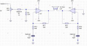
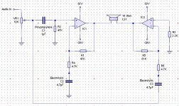
I've attached a couple of circuit diagrams to see what you guys think? The one called NS is taken from the NS document linked to chloros earlier, it turned out to be a very useful read, cheers. The circuit looks weird because it is not symmetrical and also it was designed for the LM3886, not the 3875, but it was designed by NS so it should be good.
The second I got from the image I attached earlier, it looks more promising and I'm convinced it should do 80W, not 110W. Note the pot was added by me as a volume control, is that ok or how does it affect the input impedance? The plan is to get two kits from audiosector.com, and I can build both circuits with minimal hassle from these kits.
So thanks again guys, any comments on component position or value would really be appreciated 🙂
Attachments
Last edited:
What do you mean when you say "it is not symmetrical"? One half of a bridged amp amplifies in phase ("non inverting"), the second half amplifies with exact 180 phase shift ("inverting"). E.g. IC1 of your National-Semi. circuit is the non inverting amp with an AC gain of 11x, IC2 is the inverting amp with a gain of approx. -11 (10.85...). Assume a sine signal at "Audio in" with a peak amplitude of 1 V. The highest positive voltage at the output of IC1 will be 11 V, at the very same time you will see -11 V at the output of IC2. The loudspeaker "sees" in total 22V! If both amps were of the same type (inverting or non inverting) the voltage across the loudspeaker was zero! That´s the reason why bridged amps are never totally symmetrical! The advantage of a bridged amp becomes obvious when you drive the amp to the saturation limit. With a supply voltage of +/-30V you will get +25 V at the output of IC 1 and -25 V at the output of IC2, resulting in approx. 50 V across the loudspeaker (you won´t see the full 60V due to the dropout voltage of 2x 5V, see datasheet). With a single ended amp (i.e. not bridged!) you will only get 25 V across the loudspeaker.
To be honest, I am not so comfortabel with both circuits. The left circuit ("...web-design...") wont work anyway because the inverting amp is not connected to the input signal. The second circuit ("...ns-design...") has a relatively low Z time constant consisting of C3 and R6 connected in series to a relatively high ohmic pot VR1. I would buffer the input signal after your pot with a non inverting buffer and connect it to the rest of your circuit.
To be honest, I am not so comfortabel with both circuits. The left circuit ("...web-design...") wont work anyway because the inverting amp is not connected to the input signal. The second circuit ("...ns-design...") has a relatively low Z time constant consisting of C3 and R6 connected in series to a relatively high ohmic pot VR1. I would buffer the input signal after your pot with a non inverting buffer and connect it to the rest of your circuit.
My thoughts; most of the 16 ohm speaker systems I've encountered are generally more efficient designs, so they produce higher sound output than specs would suggest, and a few more watts won't really make much difference, doubling amplifier power will only give 6dB increase in SPL, to double apparent sound output requires about 10 times the power, 25 or 30 watts might be more than enough. Also, designing a bridged amp isn't a trivial persuit, especially for a beginner, I wouldn't recommend going that way. Try it with just one chip and see if it meets your needs, I suspect it will. And if you build the 3875, don't leave out the so called "optional components" shown on the data sheet, I consider them mandatory to achieve a properly working amp.
Mike
Mike
Hmm... I see 🙂 Maybe then I should change course here a bit and go with a simpler design. I was kind of fixated on the idea of lots of power, and then reluctant to split the cross over as you suggested Andrew because it already seemed complicated enough. Perhaps I should just order a stereo kit, build it with all the extras and see how it sounds, then if I need more power I can look at splitting the crossover and getting a second stereo kit. (1 for bass, 1 for mid + tweeters)
Sounds like a plan, I'll look into kits and the other things I need (transformer, heatsink being the main ones) and no doubt I'll have more questions 😉. Cheers guys
Sounds like a plan, I'll look into kits and the other things I need (transformer, heatsink being the main ones) and no doubt I'll have more questions 😉. Cheers guys
- Status
- Not open for further replies.
- Home
- Amplifiers
- Chip Amps
- Bridged chipamp for 16Ohm speakers